background image

3

SECTION 2

INSTALLATION  INSTRUCTIONS

2.1

SAFETY PRECAUTIONS

Do not

 attempt to operate the freezer until the safety

precautions and operating instructions in this manual
are read completely and are thoroughly understood.

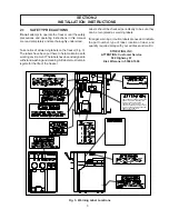
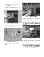
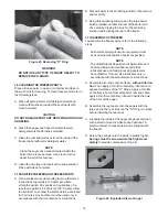
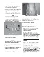
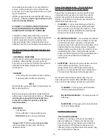
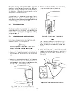
Take notice of all warning labels on the freezer (Fig. 3).
The labels have been put there to help maintain a safe
working environment. The labels have been designed to
withstand washing and cleaning. All labels must remain
legible for the life of the freezer.

Fig. 3.  Warning Label Locations

Labels should be checked periodically to be sure they
can be recognized as warning labels.

If danger, warning or caution labels are needed, indicate
the part number, type of label, location of label, and
quantity required along with your address and mail to:

STOELTING, INC.

ATTENTION: Customer Service

502 Highway 67

Kiel, Wisconsin  53042-1600

THERMISTOR.  HEAT SINK MUST BE

SEE SERVICE MANUAL.

USED WHEN BRAZING ON EVAPORATOR
OUTLET.  CHECK RESISTANCE BEFORE
REMOVAL OF THERMISTOR.

UNDER THIS COVER.  TEMPERATURE
MUST NOT EXCEED 220°F NEAR

HEAT SENSITIVE THERMISTOR LOCATED

Содержание E131G

Страница 1: ...Model E131G F131G SERVICE MANUAL Manual No 513537 3 Mar 2004...

Страница 2: ......

Страница 3: ...built prior to date of change DO NOT ATTEMPT to operate the machine until instructions and safety precautions in this manual are read completely and are thoroughly understood If problems develop or q...

Страница 4: ...ecific safety information the following safety defini tions are provided to assist the reader The purpose of safety symbols is to attract your at tention to possible dangers The safety symbols and the...

Страница 5: ...r 11 3 8 Disassembly of Freezer Parts 11 3 9 Cleaning the Freezer Parts 13 3 10 Sanitize Freezer Freezer Parts 13 3 11 Assembly of Freezer 13 3 12 Routine Cleaning 14 3 13 Preventive Maintenance 14 3...

Страница 6: ...ch Pad Switch Module Removal 38 5 14 Touch Pad Switch Module Assembly 39 5 15 Sensor 39 5 16 Sensor Removal 39 5 17 Sensor Installation 40 5 18 Preparation for Major Component Removal 40 5 19 Condense...

Страница 7: ...t 10 16 Removing Mix Inlet Regulator 11 17 Draining Mix 11 18 Auger Flight Wear and Front Auger Support Bushing Wear 11 19 Removing Front Door 12 20 Front Door Disassembly 12 21 Removing Auger Support...

Страница 8: ...32 54 Plug in Relays 36 55 Spigot Switch Replacement 37 56 Interlock Switch Removal 38 57 Interlock Switch Assembly 38 58 Switch Module Removal 38 59 Electrical Box Removal 39 60 Cover Plate Removal...

Страница 9: ...both barrels in operation If you desire to use one barrel only the freezer must be cleaned sanitized and filled with fresh mix daily For more information call your authorized Stoelting Serviceperson T...

Страница 10: ...3 8 I D drain line minimum Hopper 3 Gallons 11 35 liters each refrigerated and insulated Refrigeration N O I T P I R C S E D A R U D N E A R U T U F C A e g a t l o V V 0 3 2 8 0 2 h p 1 V 0 3 2 8 0 2...

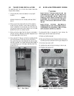
Страница 11: ...remain legible for the life of the freezer Fig 3 Warning Label Locations Labels should be checked periodically to be sure they can be recognized as warning labels Ifdanger warningorcautionlabelsarenee...

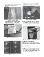
Страница 12: ...t level on top of the freezer at each corner to check for level condition If adjustment is necessary level the freezer by turning the bottom part of each leg in or out Then separate freezer base gaske...

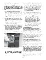
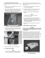
Страница 13: ...reezer to the door end of the stand Securethefreezertothestandwiththenutsandlock washersprovided Thenseparatefreezerbasegasket and install the seam to the back and the flat to the bottom Fig 7 2 5 INS...

Страница 14: ...6...

Страница 15: ...ATION Figure 9 Controls 3 2 OPERATION CONTROLSAND INDICATORS Before operating the freezer it is required that the operator know the function of each operating control Refer to Figure 9 for the locatio...

Страница 16: ...ix condition The lens will illumi nate with approximately one gallon of mix in the hopper When the MIX LOW lens is lit refill hopper immediately NOTE Failure to immediately refill hopper may result in...

Страница 17: ...a sanitized soft bristle brush dipped in the sanitizing solution Fig 13 E After five minutes place a bucket under the spigot and open spigot to drain sanitizing solution When solution has drained pre...

Страница 18: ...tandby mode sometimes referred to as a sleep or energy conservation mode When the freezer is not used after a preset time it will enter the standby mode and remain there until someone draws a product...

Страница 19: ...t and fill the hopper with 2 gallons 7 5 liters of cold tap water B Place the OFF ON switch in the ON position while pushing the CLEAN switch to rotate the auger C Allow the water to agitate for appro...

Страница 20: ...gs F Keep the rear of the auger shafts tipped up once they are clear of the freezer barrels to avoid dropping rear seals Fig 22 Figure 19 Removing Front Door G Wipe socket lubricant from the drive end...

Страница 21: ...ainer of socket lubricant is shipped with the freezer D Screw the springs onto the studs in plastic flights Springs must be screwed into the flights com pletely to provide compression Fig 24 WARNING D...

Страница 22: ...rsrequirespecialconsideration when it comes to food safety and proper cleaning and sanitizing Thefollowinginformationhasbeencompiled by Purdy Products Company makers of Stera Sheen Green Label Cleaner...

Страница 23: ...maintenance can involve a wide variety of products and procedures Overall the products and procedures fall into three separate categories Please note that this is a brief overview intended for informa...

Страница 24: ...ideal concentration of chlorine needs to be 100 ppm as stated by the FDA NOTE Follow the directions on the container for proper concentration There are two main factors that contribute to falling chl...

Страница 25: ...eration System WARNING BOTH SUCTION SIDE SOLENOIDS MUST BE ACTIVATED FOR PROPER PURGING OF SYSTEM USE POWER CORD PART NUMBER 430119 OR EQUIVALENT FOR DIRECT CONNECTION 4 1 REFRIGERATION SYSTEM The ref...

Страница 26: ...ible problems perform the following steps Warning DISCONNECT FREEZER FROM ELECTRICAL SUPPLY SOURCE BEFORE SERVICING 1 Remove the Phillips head screw from the bottom of the left side panel and slide th...

Страница 27: ...of the system and damage the compressor The condenser must be kept clean of dirt and grease The freezer must have a minimum of 3 7 5 cm of Figure 31 Electrical Box Cover Removal ventilationontheright...

Страница 28: ...gure 33 Condenser Inspection 4 5 T X V A T X V Thermostatic Expansion Valve Figure 34 is used to meter the refrigerant to the evaporator The self regulating T X V is preset at the factory Figure 34 T...

Страница 29: ...e 4 8 T X V INSTALLATION To replace the T X V perform the following proce dures CAUTION WHEN PLACING THE T X V AHEATSINK WET CLOTH MUST BE USED TO PREVENT DAMAGE TO THE VALVE 1 Position the T X V with...

Страница 30: ...g periods hopper temperatures will not drop and freeze the mix in the hopper The adjustable E P R valve is preset at the factory If the hopper temperature is too cold or too warm an E P R valve adjust...

Страница 31: ...ure of the hopper Procedures for adjusting compressor ON and OFF times will be discussed in Section 5 Figure 40 E P R Valve Adjustment 4 11 E P R REMOVAL CAUTION A HEATSINK WET CLOTH MUST BE USED TO P...

Страница 32: ...capillary tube at the end going to the hopper when the freezer is running Also the pressure reading at the E P R valve will equal suction pressure at the compressor if the tube is totally blocked 4 1...

Страница 33: ...igeration system must be leaked checked purged and evacuated to 500 microns of mercury or less at either barrel outlet access fitting preceding the suction line solenoid valves 4 16 SOLENOID VALVE Som...

Страница 34: ...clip 4 18 SOLENOID MAGNETIC COIL INSTALLATION To replace the magnetic coil perform the following procedures 1 Push the magnetic coil on the solenoid body and replace the retainer 2 Connect the two ele...

Страница 35: ...s check for adequate water supply 4 22 WATER VALVE ADJUSTMENT To determine whether or not the water valve is in need of adjustment perform the following procedures WARNING DISCONNECT FREEZER FROM ELEC...

Страница 36: ...ge to the nameplate specifications 5 Connect the water supply line and turn on the water 6 Check for leaks 7 Start the freezer and adjust the water valve 8 Replace all panels 4 25 REFRIGERANT CHARGE A...

Страница 37: ...hopperandbarreltemperature Inthis idle mode a servable consistency will not be held 5 2 POWER BOARD Thepowerboardiswheretheactualsensingofthedrive motor energy usage occurs The power board also suppli...

Страница 38: ...30 Figure 51 Power Board...

Страница 39: ...31 Figure 52 Program Module...

Страница 40: ...ght to consistency After the selected number of operating cycles the control will operate in idle mode strictly by On Off timing If the diode is not removed from the circuit the On Off timers function...

Страница 41: ...el temperature Seventh push button actuation STB Idle Temperature differential rise Eighth push button actuation Motor Slope Motor slope The rate of amperage change at cut out with respect to the rate...

Страница 42: ...Freeze switch Motor Slope The rate of amperage change at cutout with respect to the rate of line voltage change PUSH BUTTON ACTION NOTES 25 19 LKG HPR F F DIGIT DISPLAY WORD FUNCTION Ninth push button...

Страница 43: ...is a normally closed held open switch When the spigot is opened the switch will close starting the freezer 2 Push To Freeze Switch and Light The Push To Freeze switch is a normally opened snap switch...

Страница 44: ...tion Push the P T F switch to start the freezer When the drive starts release the Push To Freeze switch The freezer will run until the preset barrel temperature is reached then after the preset On tim...

Страница 45: ...y tighten the retaining screws at this time 2 Using a pencil mark the white plastic actuator below the stainless steel housing Adjust the switch to activate when the spigot handle moves the plastic pi...

Страница 46: ...bly 4 Attach the two electrical wires to the common and normally open terminals 5 Position the spigot handle assemblies in the electrical box and secure with the Phillips head screws 6 Replace the spi...

Страница 47: ...the failed side 2 Remove the Phillips head screw from the side panel and pull down and out If the failure is on the right side the back panel and side electrical box must be removed To remove the bac...

Страница 48: ...he terminal block Install the cover and secure with the two 2 Phillips head screws Figure 62 Ty raps Removal 8 Replace all panels 5 18 PREPARATION FOR MAJOR COMPONENT REMOVAL The procedure set forth i...

Страница 49: ...he fan blade so that adequate clearance is provided both to the mounting bracket and the condenser Then fully tighten the fan blade setscrew 4 Route the electrical wires to the terminal block and atta...

Страница 50: ...Wire Removal 5 24 DRIVE MOTOR INSTALLATION 1 Fit the key and pulley to the replacement motor 2 Remove the cover plate and connect the four electrical wires the replace the cover plate 3 Install the mo...

Страница 51: ...t 5 Remove the speed reducer from the freezer Then using an Allen wrench loosen the setscrew and remove the pulley and key Figure 69 Speed Reducer Removal 5 27 SPEED REDUCER INSTALLATION 1 Assemble th...

Страница 52: ...of insulating tubing on the suction line going to the compressor and unsweat the suction and discharge line from the compressor 5 Remove the four nuts and washers from the base of the compressor 6 Re...

Страница 53: ...rier 11 Purge and evacuate the refrigeration system to 50 microns of mercury for approximately 30 minutes 12 Accurately charge the system with R22 per the amount indicated on the specification tag loc...

Страница 54: ...46...

Страница 55: ...ted Contact STOELTING INC Phone 920 894 2293 502 Hwy 67 Fax 920 894 7029 Kiel WI 53042 Problem Subsection Title No __ Problem Description Page 6 1 Dispensing 6 1 1 Product dispenses slowly or not at a...

Страница 56: ...mix according to manufacturer s instructions Door handle movement is too restricted Turn dispense rate adjuster counterclockwise Door port is blocked or frozen Turn off power remove door and frozen pr...

Страница 57: ...OTE Avoid lubrication of check balls Check balls must float freely Legs are loose or freezer is not level Check legs level top of freezer Mix inlet regulator is being removed during Freezing Do not re...

Страница 58: ...achieved during freezing If not replace the cap tube 6 2 4 OVERNIGHT BARREL TEMPERATURE IS TOO WARM CAUSE CORRECTION Control idle standby STB temperature is too high Lower the idle temperature 2 to 4...

Страница 59: ...or defective Replace overload protector E111 F111 only Excessively high discharge pressure Refer to Troubleshooting Subsection 6 3 18 Internal mechanical trouble in compressor Replace compressor 6 3 6...

Страница 60: ...low voltage to unit Refer to Troubleshooting Subsection 6 3 7 6 3 10 COMPRESSOR RUN CAPACITOR OPEN SHORTED OR BLOWN CAUSE CORRECTION Excessively high line voltage 110 of rated max Contact your local...

Страница 61: ...the coarse amperage consistency procedure in subsection 3 2 Spigot switch out of adjustment or defective Adjust or replace spigot switch Condenser and or filter is dirty Clean condenser and or filter...

Страница 62: ...ively high Determine cause and correct Condenser fan and or fan motor is defective Replace fan and or fan motor Discharge line condenser tube or condenser U bend restriction especially in top half of...

Страница 63: ...fice is plugged or valve is defective Same as above Defective liquid line solenoid valve Replace coil and or liquid line solenoid valve Freezer refrigerant charge is low Refer to Troubleshooting Subse...

Страница 64: ...W TORQUE ERROR P T F LIGHT FLASHES IN SEQUENCE OF THREE NOTE Freezer ran 20 consecutive minutes without reaching consistency shutoff Refer to Troubleshooting Subsection 6 3 14 for possible causes 6 4...

Страница 65: ...to 20 minutes for auto matic reset of overload Turn power OFF then ON to clear error condition If not cleared repeat this procedure until the error condition is cleared No voltage to drive motor Resto...

Страница 66: ...58...

Страница 67: ...Brush Nylon 10 x 1 Wire Handle 208467 Brush Nylon 5 1 4 x 3 8 Wire Handle 3157992 Model ID Plate 324594 Heat Sensitive 324107 Caution Hazardous Moving Parts 324105 Danger Electric Shock Hazard 324106...

Страница 68: ...60...

Страница 69: ...61 666786...

Страница 70: ...62...

Страница 71: ...63...

Страница 72: ...64...

Страница 73: ...65...

Страница 74: ...66...

Страница 75: ...67...

Страница 76: ...68...

Страница 77: ...69...

Страница 78: ...70...

Страница 79: ...A V 8 5 7 2 2 6 7 1 K C E H C I N G A M K C E H C E V L A V 9 5 4 0 2 8 2 1 Z H 0 6 G 8 3 1 3 1 E G 8 1 1 3 1 E R O S S E R P M O C A 9 2 3 0 2 8 2 1 Z H 0 6 G 8 3 1 3 1 F G 8 1 1 3 1 F R O S S E R P...

Страница 80: ......
Отзывы: