


UM1036
Board description
Doc ID 18293 Rev 1
9/48
3 Board
description
3.1 System
architecture
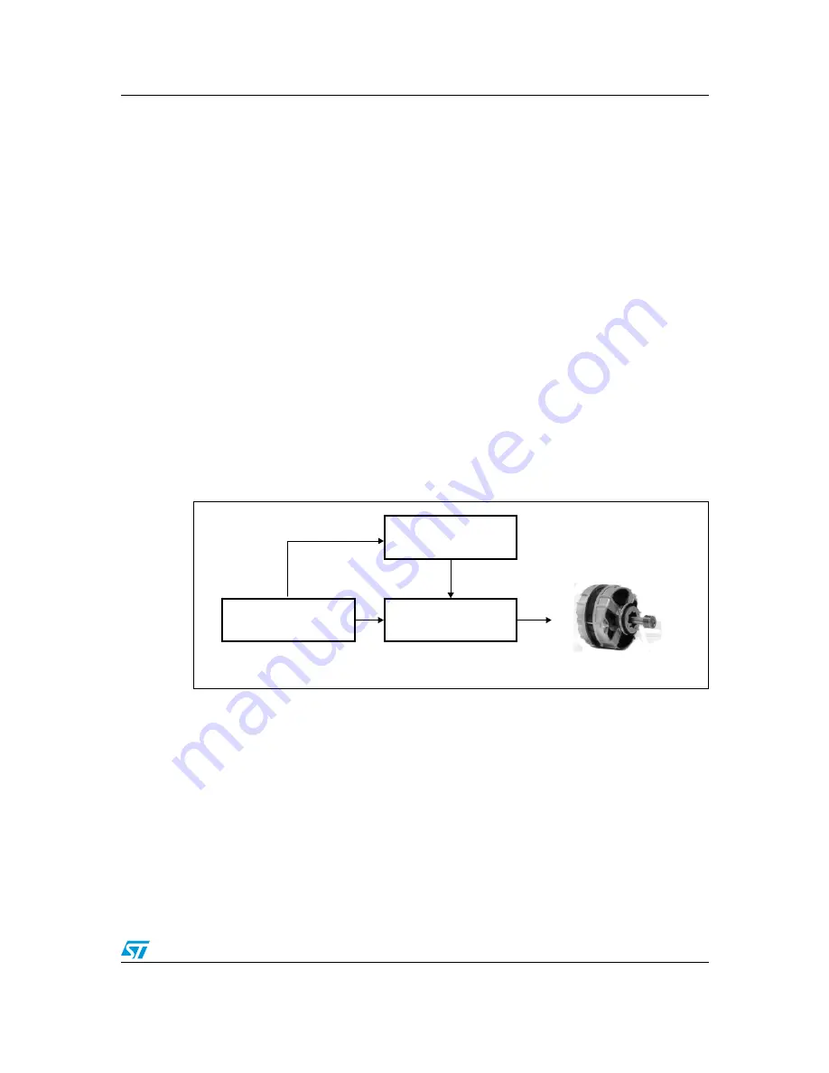
A generic motor control system can be basically schematized as the arrangement of four
main blocks (see
Figure 2
).
●
Control block
- its main task is to accept user commands and motor drive
configuration parameters. It provides all digital signals to implement the proper motor
driving strategy. The STM3210B-EVAL demonstration board, based on the STM32
microcontroller can be used as the control block, thanks to the motor control connector
equipped on the STEVAL-IHM028V1.
●
Power block
- it is based on 3-phase inverter topology. The heart of the power block is
the STGIPS20K60 integrated intelligent power module which contains all the
necessary active components. Please refer to the STGIPS20K60 datasheet for more
information.
●
Motor
- the STEVAL-IHM028V1 demonstration board is able to properly drive any
PMSM, but the FOC itself is mostly conceived for sinusoidal shaped back-EMF. The
demonstration board is also convenient for driving any 3-phase asynchronous motor.
●
Power supply block
- able to work from 90 VAC to 285 VAC or from 125 VDC to 400
VDC. The power block is based on a buck converter with a VIPer26 controller. Please
refer to
Section 4
to properly set the jumpers according to the required application.
Figure 2.
Motor control system architecture
Of the above motor control system architecture, the STEVAL-IHM028V1 includes the power
supply and the power block hardware blocks.
#ONTROLBLOCK
0OWERBLOCK
-/4/2
0OWERSUPPLY
-/4/2
!-


