39
10
06011
F4
F5
F6
F7
F2
F1
F3
ATTENTION: * Do not use jumper cables and a booster battery to start engine. Remove battery
from boat and recharge.
q
– WRONG CONNECTION WILL DESTROY ELECTRONIC SYSTEM –
* Do not charge battery in boat. Fumes vented during battery charging can lead to an
explosion.
* Battery electrolyte is a corrosive acid and should be handled with care.
If electrolyte is spilled or splashed on any part of the body, immediately flush the exposed
area with liberal amounts of water and obtain medical aid as soon as possible.
High resistance in the charging circuit can seriously affect the operation of the electrical system. Unless there is
definite malfunction in the electrical system, high resistance is sometimes caused by corroded or loose connections.
Wherever practical, the electrical connections on your engine have been sealed. However, we recommend that you
make periodic inspections to ensure clean, tight connections throughout the electrical system.
NOTE:
It is important that the battery connections are correct. The negative battery cable must be
attached to the negative terminal (
–
) on the battery and the engine’s positive cable must be
attached to the positive terminal (
+
) on the battery.
If these connections are reversed, the
regulating unit may be immediately damaged.
Inspect your battery at regular intervals for specific gravity (state of charge), individual cell water level, cleanliness
and clean, tight connections.
If the battery has become discharged for no apparent reason, check all electrical system components for malfunction,
or a switch left in ON position prior to installing recharged battery.
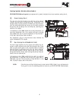
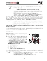
Circuit Breakers
STEYR MOTORS Marine Engine
models are protected against
overload by circuit breakers.
0
On the base plate of the E-box three thermical triggered
50 amp. circuit breakers are installed.
(F2)
protects the
electric circuit of the glow plugs of cylinder 1 & 2 (4 cyl.)
and 1 – 3 (6 cyl.);
(F3)
protects the electric circuit for the
glow plugs of cylinder 3 & 4 (4 cyl.) and 4 – 6 (6 cyl.);
(F1)
protects electric system and electronic management.
The ignition key and instruments are protected by a 10 amp.
Fuse located in the main wiring harness
under the instru-
ment panel
(at height of ignition key).
F4
Fuse supply module
F5
Fuse main circuit supply
F6
Fuse fuel-pump circuit
F7
Fuse glow-plug circuit
F9
Fuse ignition switch circuit (instrument panel)
The installation of any additional electrical accessories requires the protection of individual circuits. Consumption of
current should occur directly at the battery.
NOTE:
Avoid sparks that will damage the alternator or ECU. Do not attempt to connect or disconnect
any part of the electrical system while the engine is running.
Fuses for fuel, ECU-supply, glow plug-relay are inside the E-box cover.
Содержание MO114K33
Страница 2: ......
Страница 14: ...14 ...
Страница 46: ...46 fullload speedrange 100 90 80 70 60 50 40 30 B C D RPM A OUTPUT POWER ...
Страница 62: ...62 fullload speedrange 100 90 80 70 60 50 40 30 B C D RPM A OUTPUT POWER ...
Страница 64: ...64 ...
Страница 90: ...90 ...
Страница 106: ...106 ...
Страница 118: ...118 ...

