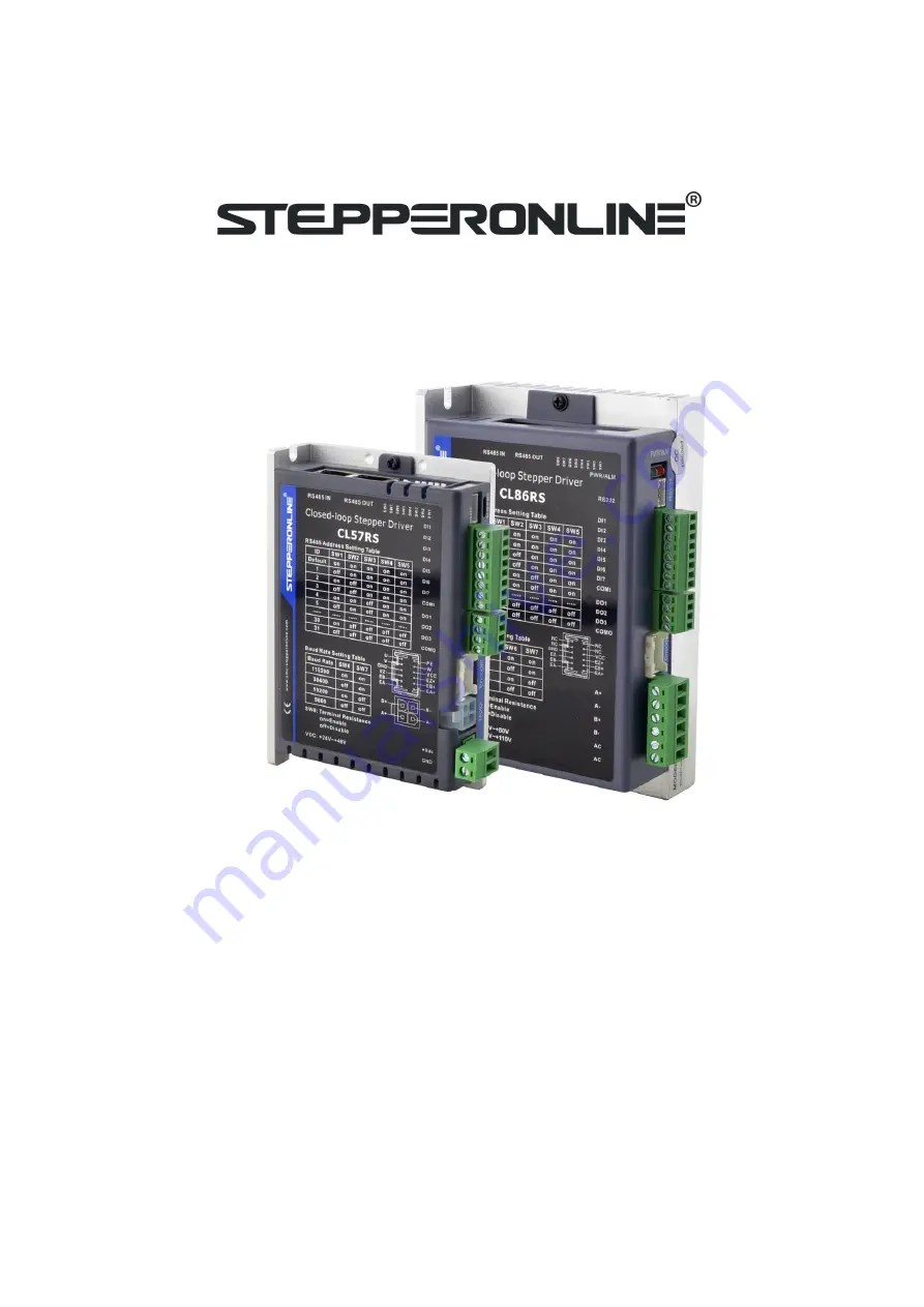
background image

User Manual

RS485 Closed Loop Stepper Drive

r

©2022 All Rights Reserved

Address:15-4, #799 Hushan Road, Jiangning, Nanjing, China

Tel: 0086-2587156578

Web: www.omc-stepperonline.com

Sales:[email protected]

Support: [email protected]

Содержание CL57RS

Страница 1: ...losed Loop Stepper Driver 2022 All Rights Reserved Address 15 4 799 Hushan Road Jiangning Nanjing China Tel 0086 2587156578 Web www omc stepperonline com Sales sales stepperonline com Support technica...

Страница 2: ...STEPPERONLINE While every precaution has been taken in the preparation of the book STEPPERONLINE assumes no responsibility for errors or omissions Neither is any liability assumed for damages resulti...

Страница 3: ...ling a cover to prevent accidental touching by hands and parts cables etc Use double insulated or reinforced insulation for control power Do not use in places where water can be splashed Corrosive env...

Страница 4: ...fied direction Make sure to keep the specified intervals between the inner surfaces of the drive control cabinet and other machines Do not pass the magnetic contactor in the wiring between the drive a...

Страница 5: ...llation Direction and Space 6 3 Product Specifications 8 3 1 Electrical and Operating Specifications 8 3 1 1 Electrical and Operating Specifications 8 3 2 Wiring Instructions 9 3 2 1 Power Cable Encod...

Страница 6: ...Troubleshooting 26 4 4 3 Error Clear 27 4 5 Register Mapping Continuous Read Write Function 28 4 6 S code Application 29 4 7 Enable Drive 30 5 PR Mode Indexer Table 30 5 1 PR Main Features 30 5 2 Homi...

Страница 7: ...ion of Trial Run 46 6 1 3 Operation of PR Function 47 6 2 Basic Operation of Serial Port Tools Software 49 6 2 1 Preparation and Steps 49 6 2 2 Operation Instruction Format 50 6 2 3 Command Cases of M...

Страница 8: ...nputs 3 optically isolated digital outputs Limit Limit Origin Quick stop Enable JOG JOG and Position Table inputs Alarm Brake Homing complete In Position complete instructions complete Path complete o...

Страница 9: ...d HMI have RS485 communication so user can choose one or both Using PLC can write more complex programs to let motion more intelligent and the HMI can monitor and modify the drive parameters in real t...

Страница 10: ...ransportation Check the nameplate models of the drive and motor are what you have ordered Cheek if it is fully equipped with accessories Accessories include power supply and I O signals connector 1 4...

Страница 11: ...3m 5m 8m 10m 12m 15m Motor Side Manufacturer TE Housing 172159 1 4P Terminal 770904 1 Drive Side Manufacturer Molex Housing 39012040 Terminal 39000038 Encoder extension cable Yes CABLEM BM M Optional...

Страница 12: ...ondensed Avoid any type of exposure to corrosive gases 2 1 2 Operating ambience conditions Temperature ranging from 0 to 50 The ambient temperature of drive for long term reliability should be under 4...

Страница 13: ...nstallation may result in a drive malfunction or premature failure of the drive and or motor Please follow the guidelines in this manual when installing The drive should be mounted perpendicular to th...

Страница 14: ...7 CLRS Series RS485 Closed Loop Stepper Drive User Manual Figure 2 2 CLRS series installation drawing...

Страница 15: ...ble Error etc PC Software STEPPERONLINE ProTuner coming soon Operating Environment Environment Avoid dust oil fog and corrosive gases Operating Temperature 0 50 32 F 122 F Storage Temperature 20 65 4...

Страница 16: ...VDC GND A A B B terminal wire diameter 0 3mm2 AWG15 22 EA EA EB EB EZ EZ VCC GND wire diameter 0 15mm2 AWG26 Recommend to adopt shielded twisted pair cables 3 2 2 I O Signal Cable Wire diameter I1 I7...

Страница 17: ...tor CN2 Motor connector CN3 I O signals connector CN4 RS485 communication connector CN5 RS232 tuning connector CN6 Encoder Signals Connector DIP Switch Salve ID SW1 SW5 Baud Rate SW6 SW7 Terminal Resi...

Страница 18: ...Name Pic PIN Signal I O Description CN4 1 DI1 I Configurable Single ended Digital Inputs DI1 DI7 12V 24V DI1 is enabling signal default DI2 DI7 are GPIOs 2 DI2 I 3 DI3 I 4 DI4 I 5 DI5 I 6 DI6 I 7 DI7...

Страница 19: ...CN5 1 NC 2 TxD 3 GND 4 RxD 3 3 6 CN6 Encoder Input Signals Connector Name Pic PIN Signal Description CN6 1 2 3 4 NC Reserved 5 EA Encoder signal of phase A 6 EA Encoder signal of phase A 7 EB Encoder...

Страница 20: ...n 11 off off on off on 12 on on off off on 13 off on off off on 14 on off off off on 15 off off off off on 16 on on on on off 17 off on on on off 18 on off on on off 19 off off on on off 20 on on off...

Страница 21: ...ast slave in the network needs to connect a 120 terminal resistance it means set the SW8 to on 3 4 I O Connection 3 4 1 Digital Inputs The connections of input signals are as below Figure 3 3 Input In...

Страница 22: ...ndor to configure this output as a BRAKE CONTROL output In this case brake signal can be used for automatic brake control while system power failure It is recommended to connect a fly wheel diode in p...

Страница 23: ...s Parameter setting Function code FC Function code FC Function 0x03 Read single or multiple data 0x06 Write value to single data 0x10 Write value to multiple data Check Mode CRC 16 Left is Low bit Rig...

Страница 24: ...13 Details as following Master slave data Message 01 03 01 BC 00 06 05 D0 Description Slave ID FC Register address Number of registers read CRC Slave master data Message 01 03 0C 00 00 00 02 00 00 00...

Страница 25: ...FC 06 Address of register to write to High Address of register written to High Low Low Value to write High Value written to register High Low Low CRC Low CRC Low High High Example C Write the value of...

Страница 26: ...irst register to write to High Address of first register written to High Low Low Total number of registers to write to High Total number of registers written to High Low Low Number of data bytes in me...

Страница 27: ...rdless of the IO signal status 0 1 0 0x0051 Pr1 00 Position loop Kp Increase this value will reduce position following error but could result in motor vibration 0 3000 507 25 1008 45 0x0053 Pr1 01 Vel...

Страница 28: ...n number of pulses to send out the In Position signal 0 1500 200 CPR 0x0177 Pr4 27 Bus voltage 0 65535 0 0 1V 0x0179 Pr4 28 Digital input statue Bit0 Bit6 SI1 SI7 0 65535 0 0x017B Pr4 29 Digital outpu...

Страница 29: ...7 100 1ms 0x0237 Pr7 03 Current loop proportional KP Invalid 0 3000 1500 0x0239 Pr7 04 Current loop KI It is recommended to keep the factory value when disable auto tuning can be modified 0 1500 300 0...

Страница 30: ...ote 1 If the input or output function is set repeatedly only after the restart drive can detect it 2 When input functions are configured it is effective after clicking save and restart drive Digital I...

Страница 31: ...write 0 by default Register Value Filtering time unit ms 0000 10 0001 1 0010 2 0011 3 0100 4 0101 5 0110 6 0111 8 1000 15 1001 20 1010 30 1011 40 1100 50 1101 100 1110 200 1111 500 Note 1 The values...

Страница 32: ...low 16 bit Profile velocity R rpm 0x1046 high 16 bit 0x1047 low 16 bit Feedback velocity R rpm 4 3 5 Control Word and Status Word 1 The related function is started by sending the control word 2 The c...

Страница 33: ...or example write data over limit value etc 0x08 Wrong CRC check code Example F CRC check code error Master slave data Message 01 03 00 01 00 01 D5 C1 Description Slave ID Function code Register addres...

Страница 34: ...eck whether the motor wire is broken 0x200 EEPROM error 5 1 Connect the drive to STEPPERONLINE software to reset parameters to the factory 2 If it still exists the hardware failure 0x100 Auto tuning e...

Страница 35: ...brake 0x0F15 0x0173 Pr4 25 software de jitter delay of position when in position 0x0F16 0x0233 Pr7 01 encoder resolution 0x0F17 0x0243 Pr7 09 over voltage threshold 0x0F18 0x602E Pr8 46 digital inputs...

Страница 36: ...id keep last value 1 Effective Recommended S code at completion Whether the start S code is valid or not 0 Invalid 1 Effective Recommended S code at start up bit7 and bit15 are set to 1 The rest of th...

Страница 37: ...ing The drive can detect zero position by homing processing and confirm the zero point of mechanical coordinate system Select homing method by limit switch signal by home switch signal auto homing aft...

Страница 38: ...switch signal homing by detecting home switch signal set zero position by manual auto homing after powering on Zero Position a fixed position on the machine can correspond to a definite digital input...

Страница 39: ...signal index signal Note 1 Write 0x21 to the address 0x6002 to set the current point to zero position 2 Write 1 to the bit2 of address 0x6000 can set to auto homing after powering on Pr8 11 0x600B Ho...

Страница 40: ...33 CLRS Series RS485 Closed Loop Stepper Drive User Manual 2 Home Switch at Positive Direction 3 Home Switch Negative Limit Switch...

Страница 41: ...34 CLRS Series RS485 Closed Loop Stepper Drive User Manual 4 Home Switch at Negative Direction 5 2 3 Homing by Limit Switch 1 Positive Limit Switch 2 Negative Limit Switch...

Страница 42: ...bits 0x6008 Pr8 08 Soft limit H 32767 0x8000 Soft limit negative high bits 0x6009 Pr8 09 Soft limit L 32767 0 Soft limit negative low bits 0x6016 Pr8 22 Soft limit quick stop time Deceleration time a...

Страница 43: ...elocity switching During the is running the value of velocity can be modified and effect in real time The path motion can also be triggered by external IO SI1 is set to enable input by default normall...

Страница 44: ...00 0x6200 PR path 0 The corresponding functions can be selected for different bit Bit0 3 Operation mode 0 no action 1 position mode 2 velocity mode 3 homing mode Bit4 INS 0 No interrupt 1 interrupt al...

Страница 45: ...configured as any one of ADD0 ADD3 then combine the path numbers as shown in the table below on means the digital input is configured as ADDx x 1 3 and the input signal optocoupler on off means signal...

Страница 46: ...Jump For example set paths 5 and 9 set path 5 to jump to path 9 Multi segment jump path sequence diagram Continuous movement The bit5 of Pr9 00 is 0 which does not overlap the continuous path As show...

Страница 47: ...terrupting and abandoning the current path under trigger and runs another path directly which is similar as Interrupt priority of function As below example interrupt the PR1 PR path1 to run PR2 PR oat...

Страница 48: ...on means signal input on off means signal input off IO running path SI1 ADD0 SI2 ADD1 SI5 CTRG Path 0 off off on Path 1 on off on Path 2 off on on Path 3 on on on 5 5 2 IO Combination Trigger The conf...

Страница 49: ...d Steps as below 1 Firstly configure required homing and path it can be set through controller PLC software after power on or through STEPPERONLINE PC software 2 Enable drive 3 Write corresponding com...

Страница 50: ...urn message Slave Master 1 ID Slave ID 0 31 ID Sub station No 0 31 2 FC Function code 0x10 FC Function code 0x10 3 ADDR Address 0x62 ADDR Address 0x62 4 0x00 0x00 5 NUM1 Number of Word 0x00 NUM Actual...

Страница 51: ...3 10 which supports Windows 7 and Windows 10 systems 6 1 1 Preparation and Steps 1 RS232 Tuning cable CABLE PC 1 Pin Definition It is recommended that users order this cable directly from STEPPERONLI...

Страница 52: ...45 CLRS Series RS485 Closed Loop Stepper Drive User Manual 5 Basic parameter setting 6 Input and output function and polarity setting...

Страница 53: ...lick OK Then in the parameter management window click the Save button to prevent the parameter values from being lost after the drive is powered off 6 1 2 Operation of Trial Run Trial run lets the mot...

Страница 54: ...r Manual 6 1 3 Operation of PR Function 1 This window can set the CTGR trigger and Homing parameters of PR motion 2 This window is the PR path parameter setting including operation mode target positio...

Страница 55: ...o download and save as follows 3 Manually run the PR path As shown in the figure below the default is the motion parameter of PR0 As long as click Start the motor will run according to the path of PR0...

Страница 56: ...erial Port Tools Software This is to control the motor through RS485 communication user can realize the movement of the motor by sending commands to the corresponding registers 6 2 1 Preparation and S...

Страница 57: ...mple of setting the PR0 path Data is in hexadecimal Slave ID Function Code Register Address Value to Write CRC 01 06 Preset single register 62 00 PR0 operation mode setting 00 41 Set PR mode to relati...

Страница 58: ...66 3F Set PR0 speed value 01 06 60 02 00 10 37 C6 Trigger PR0 motion Send when you need to stop 01 06 60 02 00 40 37 FA Emergency stop 4 Set PR1 to go absolute position mode running distance 200000p...

Страница 59: ...stiffness 0 3000 507 25 1008 45 0x0065 Pr1 10 Position loop KpH Usually keep default 0 3000 0 0x00A1 Pr2 00 Command filter time To configure the time for internal command filtering 0 512 15 0 1ms 0x0...

Страница 60: ...Pr5 04 Shaft locked duration Keep default normally 0 1500 200 1ms 0x019F Pr5 07 Rising time of shaft locked current power on Keep default normally 1 60 1 100ms 0x01A5 Pr5 10 The max stop time Keep def...

Страница 61: ...one parameter occupies one register one 16 bit register 2 8 bit bytes Parameter NO in PC software Register Address Name Description Pr8 00 0x6000 PR global control function Bit0 CTRG effective edge 0...

Страница 62: ...Limit switch error during homing 0x102 Homing over travel error 0x20P Limit switch error in Path P P 1 15 0x300 Touch limit switch during JOG movement Pr8 38 0x6026 JOG velocity 2 JOG triggered by ex...

Страница 63: ...th 0 maps directly to Pr8 02 Others are reserved Pr9 08 0x6208 Motion of Path 1 Pr9 09 0x6209 Position H Pr9 10 0x620A Position L Pr9 11 0x620B velocity Pr9 12 0x620C Acc Pr9 13 0x620D Dec Pr9 14 0x62...

Отзывы: