background image

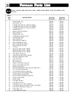
When  ordering  replacement  parts,  please  include  model  number  and  serial  number  of  the 
furnace. 

DWG. 

REF. 

DESCRIPTION 

DLF30B 

DLF40B 

NO. 

ITEM  NO. 

ITEM  NO.


1. 

Painted Panel, Top 

5940053 

5940053 

2. 

Galvanized Top 

5940055 

5940055 

3. 

1" Blanket Insulation, Top & Front (Outer) 

1050030 

1050036 

4. 

2" Blanket Insulation, Top & Front (Middle) 

1050031 

1050037 

5. 

2" Blanket Insulation, Top & Front (Inner) 

1050032 

1050038 

6. 

Aluminized Top 

5940062 

5940062 

7. 

Stainless Steel Panel, Back 

5940179 

5940180 

8. 

Spacer  Bracket 

5940092 

5940092 

9. 

Painted  Panel,  Left 

5940056 

5940057 

10. 

Aluminized Steel Panel, Front 

5940270 

5940271 

11. 

Painted Panel, Front 

5940049 

5940050 

12. 

Galvanized Front 

5940059 

5940060 

13. 

Galvanized Air Deflector 

5940188 

5940189 

14. 

Galvanized Back & Sides 

5940069 

5940035 

15. 

Heat  Storage  Brick (Whole) 

5903002 

5903002 

Heat  Storage  Brick (Half) 

5903001 

5903001 

16. 

Air Filter 

1159012 

1159012 

17. 

Heating Element (240V, 3200W) 

1014016 

1014016 

Heating Element (208V, 3200W) 

1014018 

1014018 

Heating Element (277V, 3200W) 

1014020 

1014020 

18. 

Filter Rack ­ Return Air 

1022010 

1022010 

19. 

Sequencer/Element  Wiring  Harness 

1040021 

1040006 

20. 

Hard Board Insulation, Base 

1050060 

1050061 

21. 

Tray  Assembly 

5940151 

5940151 

22. 

Base  Panel,  Left 

5940154 

5940154 

23. 

Electrical  Panel 

5940176 

5940176 

24. 

Stage 2 Time Delay Sequencer 

1019000 

1019000 

25. 

Stage 3 Time Delay Sequencer 

1019004 

1019004 

26. 

Charging  Sequencers 

1019002 

1019002 

27. 

Heat Exchanger High Limit Switch Assembly (54") 

1040058 

1040058 

28. 

75 VA Control Transformer 

1017039 

1017039 

29. 

Volt Reduction Resistor Assembly 

1040047 

1040047 

30. 

Charge Control Circuit Board (SFIII) 

1023005 

1023005 

31. 

Control Board Mounting Plate 

5940140 

5940140 

32. 

Charge Control Thermostat Assembly 

1040033 

1040033 

33. 

Charge Control Knob 

1154004 

1154004 

34. 

Blower Relay 

1018008 

1018008 

35. 

Fan Speed Resistor 

1017030 

1017030 

36. 

Core  Blower  Wheel 

1020002 

1020002 

37. 

Core  Blower  Cover  Plate  Assembly 

5940120 

5940120 

38. 

Core Blower Motor Assembly (1/6 HP, 1360 RPM) 

1040085 

1040085 

39. 

Core Blower Motor Run Capacitor 

1018004 

1018004 

40. 

Front Angle, Top 

5940046 

5940046 

41. 

Circuit Breaker Standoff 

5940034 

5940034 

Furnace  Parts  List 

NOTE 

26

Содержание DLF30B

Страница 1: ...DLF4 OWNER S AND INSTALLER S MANUAL for Double Loop Central Furnaces Manufactured in North America U S Pat 5201024 Can Pat 2060881 Models DLF30B DLF40B ...

Страница 2: ...he Furnace OFF and ON 8 Installing the Furnace Shipping 9 Placement 9 ClearanceRequirements 10 Furnace Set up 10 12 BrickLoading 12 13 InstallingtheHeatingElements 13 Ducting 13 14 Line VoltageElectrical Connections 15 18 LowVoltageElectrical Connections 19 22 Furnace Final Test Procedure 23 Furnace Specifications 24 Exploded View Parts Diagram 25 Furnace Parts List 26 27 Troubleshooting Informati...

Страница 3: ... quick reference to these numbers DISCLAIMER Incompiling this manual Steffes Corporationhas usedits bestjudgementbased uponinfor mationavailablebutdisclaimsanyresponsibilityorliabilityforanyerrorsormiscalculationscontainedherein or anyrevisions hereof or which result whole or in part from the use of this manual or anyrevisions hereof 2 General Information GENERAL OPERATION TheSteffesETSDoubleLoopC...

Страница 4: ...tdoor temperature Off Peak The time during the day or night when the power company can supply electricity more economically and may offer a special incentive such as a reduced electric rate or billing credits for the electricity consumed during this time Typically uncontrollable electrical usage is allowed during this time Furnace is allowed to charge or store heat in its brick core during this ti...

Страница 5: ...perature is exceeded Each switch controls two heating elements In the limit bar panel on the right side of the brick storage cavity This limit switch monitors the temperature in the heat exchanger of the furnace If the normal operating tempera ture is exceeded this switch will interrupt power to the core blower Heat Exchanger High Limit Switch In the base of the furnace inside the electrical panel...

Страница 6: ...designate the brick core charge level the furnace is targeting whenever the elements are allowed to be ON Refer to Table 1 Brick Core Charging Schedule in this manual for more informa tion on charging levels in relation to outdoor temperature and the furnace control panel settings LEVEL 1 Illuminates when the furnace is targeting a heat storage setting of approximately 1 3 core charge 500o F nomin...

Страница 7: ...junction with START and CANCEL toggle switches START and CANCEL Toggle Switches Override Feature Power Company Permitting The furnace has a built in peak override feature This feature allows the heating elements in the furnace to come ON during a peak control time provided the power company permits the use of this option Since not all power companies permit use of the override option all furnaces ...

Страница 8: ...tion of heat into the living area Some thermostats incorporate a room temperature set back feature which allows for room temperature to automatically be set back a specific number of degrees at specified times If using a thermostat with this feature in a program where the power company has 8 or more consecutive hours of control it is important to bring the room temperature back to the desired occu...

Страница 9: ...level The outside temperature must drop below 35o F before core charging will occur Refer to Table 2 Brick Core Charging Schedule in this manual for more information on charging levels in relation to outdoor temperature and the furnace control panel settings If during off peak hours the wall thermostat calls for heat and the outdoor temperature is above 55o F 1 3 of the elements will be energized ...

Страница 10: ...y air blower plenum assem bly box PLACEMENT The physical dimensions of the furnace along with the clearances required must be taken into consideration when choosing a location for the furnace The minimum area needed for the installation of a furnace is 100 square feet The best installation location for the furnace is in an area it will be heating Although most of the heating requirements of the sp...

Страница 11: ... UP For cross reference to number coded components see the Exploded View Diagram and the Furnace Parts List in this manual Refer to Table 2 in the Shipping section of this manual for a list of items each furnace should contain Step 1 Unbox the brick storage cabinet Step 2 Remove painted front panel 11 of cabinet by removing the sheet metal screws on the lower edge Rotate bottom edge of panel out t...

Страница 12: ...tions on the furnace Step 10 Install the sides and back painted outer panels 9 71 73 on the brick storage cavity Use the screws found in the hardware package to secure the panels to the cabinet by placing them along bottom edge of the panels To avoid internal wire damage use only blunt tip screws in all areas where screw tips could come in contact with wiring Step 11 Install the temperature sensin...

Страница 13: ...anel 10 by pulling out at the top Step 4 Remove the heating elements 17 and the packing material from the brick core cavity To ensure adequate room for brick loading the top or bottom 1 x 4 nominal wooden core spacer can be used to hold inner brick cavity walls apart The core spacer is packaging material and can be discarded after brick loading is complete Step 5 To minimize the amount of brick de...

Страница 14: ...nt aluminized steel panel 10 This panel MUST be installed with its air deflectors arrow shaped pieces facing inward and with the narrow ends of the deflectors pointing up Step 4 Lower the insulation blankets 3 4 5 back into position one at a time Carefully tuck the sides of this insulation into the edges corners and around the exposed portions of heating elements 17 Step 5 Replace the galvanized f...

Страница 15: ...Attach the front access cover to the plenum Step 5 Attach the supply air blower plenum assembly 60 to the furnace by drilling two 1 8 holes per edge Attach to the furnace supply air side using the blunt tip screws supplied in the hardware package Step 6 Secure the filter rack assembly 18 on the return air side again by drilling 1 8 holes per edge and using the blunt tip screws supplied in the hard...

Страница 16: ... If single feed of the charging element circuits is desired an optional single feed kit is available from the factory Order item 1309000 The single feed kit enables the furnace to be fed with a single circuit which then splits this circuit internally to each breaker All line voltage circuits must be segregated from low voltage wiring in the furnace To determine the correct wire size required for e...

Страница 17: ...ENCOR STAGE 2 CHARGING SEQUENCOR STAGE 3 CHARGING SEQUENCOR N C HEAT EXCHANGER LIMIT 180 LIMIT 190 LIMIT 135 FAN CONTROL N C N C N O CORE BLOWER N O COM HOUSE BLOWER N C N O COM 240v 24v 75VA TRANSFORMER 10uf Cap SUPPLY AIR BLOWER HIGH MED HIGH MED LOW LOW COM CORE BLOWER HIGH LOW COM 5uf Cap HEATING ELEMENTS HEATING SPEED BLUE RED COOLING SPEED BLUE BLACK SEE NOTE 1 N C N O COM 170 DISK Switches ...

Страница 18: ...MIT 190 LIMIT 135 FAN CONTROL N C N C N O N O CONTROL 135 FAN CIRCUIT 4 CHARGE BLOWERS CIRCUIT CHARGE CIRCUIT 1 CHARGE CIRCUIT 2 CHARGE CIRCUIT 3 350 350 350 350 350 350 RED WHITE STAGING 3 1 2 3 1 2 3 1 2 3 1 2 N O N O N O N O N O N O N O N O 15A 60A 60A 60A 60A STAGE 1 CHARGING SEQUENCER STAGE 2 CHARGING SEQUENCER STAGE 3 CHARGING SEQUENCER 240v 24v 75VA TRANSFORMER 10uf Cap SUPPLY AIR BLOWER HI...

Страница 19: ...E 1 N O N O N O N O N C LIMIT 160 3 1 3 2 2 1 1 3 STAGING 2 BLACK BLUE RED 240v 24v GROUND LUGS YELLOW 277 VAC YELLOW CORE TRANSFORMER BLOWER N O 75VA HOUSE BLOWER N O N C COM 135 FAN CONTROL CONTROL 135 FAN N C LIMIT 180 N O N O COM CIRCUIT 1 COMMON 277 VOLT 60 60 CIRCUIT 1 240 VAC CIRCUIT 2 277 VAC BLACK on temp rise 170 DISK Switches to low N C R1 RED 125 COM N O BROWN BLACK LOW COM HIGH N C E1...

Страница 20: ...t and peak control signal are low voltage wire connections to the furnace All low voltage wiring must be segregated from line voltage circuits in the furnace Low Voltage Wiring Diagram 9 NOTES 1 Low voltage auxiliary control contacts a Y to Y2 contacts open when load control device closes b Y to Y3 contacts close when load control device closes 2 Auxiliary contacts close during off peak heat calls...

Страница 21: ... route the low voltage wire from the sensor to the furnace Step 3 Route the wire into the furnace s electrical compartment and up to the charge control circuit board 30 Never install any wiring in the line voltage compartment of the furnace unless it is rated for line voltage Step 4 Connect the sensor to the 4 position terminal strip on the bottom front of the charge control circuit board 30 The w...

Страница 22: ...any wiring in the line voltage compartment of the furnace unless it is rated for line voltage Step 4 Connect the thermostat to the 4 position terminal strip on the top front left corner of the charge control circuit board 30 labeled R W G and C See Figure 13 for reference to room thermostat connections to the furnace Step 5 If the thermostat has an anticipator set it to 5 amps Installing The Furna...

Страница 23: ...tch will signal an on peak time to the furnace charging is disabled N C An open power company switch will signal an off peak time to the furnace charging is enabled A closed power company switch will signal an on peak time to the furnace charging is disabled Optional Features These recommended wiring methods reflect only devices that accept a remote low voltage power source Refer to the specific i...

Страница 24: ...ep 7 if the peak override feature is not avail able to you ____ 7 With unit in the on peak mode depress the override START switch and observe the OVERRIDE indicator light The light should be illuminated ____ 8 Remove the jumper between the W and R outdoor sensor connection terminals and reconnect the outdoor air temperature sensor 64 Set the selector switches to the AUTO and WINTER positions ____ ...

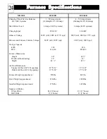
Страница 25: ...ols Voltage 240V std 208V opt 240V std 208V opt Storage Capacity kWh 180 240 BTU 614 160 818 880 Furnace Dimensions Height 60 69 Width without ducting 35 35 Depth 49 49 Air Duct Dimensions Supply Air Duct W X D opening 18 X 21 18 X 21 Return Air Duct H X D opening 15 X 24 15 X 24 Furnace Weight approximate 590lbs 642lbs Brick Weight approximate 2160lbs 2808lbs Installed Weight approximate 2750lbs ...

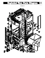
Страница 26: ...Exploded View Parts Diagram 25 FIGURE 17 ...

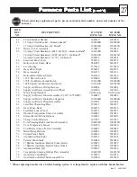
Страница 27: ... Element 277V 3200W 1014020 1014020 18 Filter Rack Return Air 1022010 1022010 19 Sequencer Element Wiring Harness 1040021 1040006 20 Hard Board Insulation Base 1050060 1050061 21 Tray Assembly 5940151 5940151 22 Base Panel Left 5940154 5940154 23 Electrical Panel 5940176 5940176 24 Stage 2 Time Delay Sequencer 1019000 1019000 25 Stage 3 Time Delay Sequencer 1019004 1019004 26 Charging Sequencers 1...

Страница 28: ... 1 2 HP 1075 RPM 1040086 1040086 59 Supply Air Blower Motor Run Capacitor 1018006R 1018006R 60 Supply Air Blower Plenum Assembly 1022008 1022008 61 Limit Bar Channeling Plate 5940167 5940167 62 Base Panel Back 5940156 5940156 63 Limit Bar Louvre Panel 5940152 5940153 64 Outdoor Temperature Sensor Assembly 1040031 1040031 65 Element LimitWiringHarness 1040022 1040005 66 Charge Control Resistor 1017...

Страница 29: ... limit bar louvre area See drawing reference 68 in the Exploded View Parts Diagram The millivolt reading DC can be compared to the Core Temperature Graph below to correlate the reading to an approximate brick core tempera ture This reading is useful in determining proper core charging of the furnace 1 0 5 10 15 20 25 30 1400o 1200o 1000o 800o 600o 400o 200o Core Temperature o F Millivolts DC Maxim...

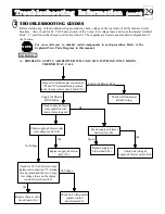
Страница 30: ... ROOM THERMOSTAT CALL 2 NOTE Jumper room thermostat connections R and G terminal block positions in the charge control circuit board 30 Check supply air blower relay operation 34 Lower relay in panel Supply Air Blower Will Not Run Check wall thermostat field wiring Supply Air Blower Runs Check supply air blower relay coil voltage for 24 VAC Check supply air blower limit switch 54 Ok Check for 24 V...

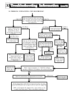
Страница 31: ...efective control transformer 28 Check heat exchanger and core blower limit switches 27 53 core blower speed switch 69 Check core blower relay coil voltage for 24 VAC Core Blower Runs Core Blower Does Not Run Core Blower Does Not Run Ok Inoperable Replace defective switch es Check core blower motor 38 unit wiring Replace core blower relay 34 Replace charge control circuit board 30 Ok No Voltage Ok ...

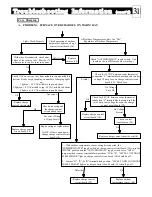
Страница 32: ...ck for 24 VAC between room thermostat connection C terminal block position and the two 3 amp low voltage fuses on the charge control circuit board 30 Replace charge control thermostat Check control transformers 28 Replace charge control circuit board 30 No Voltage Present Ok Replace charge control circuit board 30 Ok 1 With outdoor temperature sensor wiring disconnected the SUMMER WINTER toggle sw...

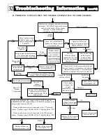
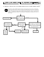
Страница 33: ...rmostat shaft is in the full clockwise position Check outdoor temperature Set the AUTO HIGH LOW toggle switch on charge control circuit board 30 to high position Check supply voltage to the control transformer s 28 and unit wiring Set the AUTO HIGH LOW toggle switch to AUTO and the SUMMER WINTER toggle switch to WINTER positions on the charge control circuit board 30 1 Remove outdoor sensor wire c...

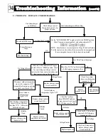
Страница 34: ...ng Incorrect Ok Charge Light ON Check continuity across the red and yellow thermocouple wires Replace auxiliary control relay board Charge Light OFF Replace the thermocouple Contact Steffes Technical Support No Continuity Continuity NOTE This portion of the troubleshooting flow chart is to test operation of the auxilairy control board Furnaces built after January of 1998 were produced with this ad...

Страница 35: ...sequencers 26 Disconnect outdoor temperature sensor 64 connection W terminal block position on charge control circuit board 30 Replace charge control circuit board 30 Less Than Proper Amperage Ok No Voltage Present Voltage Present Check for contact closure on all charging sequencers 26 Check the outdoor temp SENSOR lights on charge control circuit board 30 All three must be ON Ok Replace sequencer...

Страница 36: ...o an applianceor part which has been altered inany respect or improperly installed serviced or used or has been subject to accident negligence abuse or misuse THE ABOVE WARRANTY BY STEFFES IS EXCLUSIVE AND IN LIEU OF ALL OTHER WARRANTIES WHETHER WRITTEN OR ORAL EXPRESS OR IMPLIED INCLUDING ANY IMPLIED WARRANTY OF MERCHANTABILITY OR OF FITNESS FOR A PARTICULAR PURPOSE The user assumes all risk and ...

Отзывы: