


¢
The second to last row, front,
middle brick must be the last
brick installed. A shim may be
used to hold the upper brick in
place, or it is more easily
accomplished by leaving the
middle brick in the second to
last row pulled about 4"
forward from its intended
position. In this position the
brick will act as a support for the top middle brick. Push the front, middle brick in the second to
last row into place which will at the same time push the middle brick that was left forward into
place. (See Figure 7 for a picture depiction of this procedure.)
INSTALLING THE HEATING ELEMENTS
Step 1
After all bricks are loaded, insert the heating elements (17) between the brick layers with the cold
pins facing up. (See picture depictition of element termination in Figure 6 for reference to cold pin
direction.)
Step 2
Make the heating elements (17) to wiring harness (19 & 65) connections. (See Figure 6 for a picture
depictition of element termination.)
Use two 3/8" wrenches to ensure tight connections and to avoid twisting the
threaded element cold pins off.
Step 3
Replace the front aluminized steel panel (10).
This panel MUST be installed with its air deflectors (arrow shaped pieces) facing
inward and with the narrow ends of the deflectors pointing up.
Step 4
Lower the insulation blankets (3, 4, & 5) back into position, one at a time. Carefully tuck the sides of
this insulation into the edges, corners, and around the exposed portions of heating elements (17).
Step 5
Replace the galvanized front panel utilizing the original #8 x 1" sheet metal screws that were re
moved.
Step 6
Replace the painted front panel (11) using blunt tip screws only.
DUCTING
Air Flow
The Steffes furnace has been specially designed for versatility and may be installed to meet righttoleft or left
toright air flow requirements. The furnace is factory configured for a lefttoright air flow. If it is desired to
reverse the air flow, do the following:
Step 1
Reroute the supply air blower wiring harness (55) to the opposite side of furnace base by fishing the
harness between bottom radiant heat shield (51) and bottom panel (47). Be sure to route the wiring
harness away from the heat exchanger and place any excess wiring between the radiant heat shield
(51) and bottom panel (47).
7
Installing The Furnace
(cont'd)
13
6
NOTE
NOTE
FIGURE 7
LAST (TOP) ROW
SECOND TO LAST ROW
MIDDLE BRICK
Содержание DLF30B
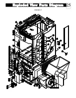
Страница 26: ...Exploded View Parts Diagram 25 FIGURE 17 ...


