


0" REQUIRED
CLEARANCE
2" MIN
CLEARANCE
3" MIN CLEARANCE
36" MIN CLEARANCE
TOP VIEW
0" REQUIRED
CLEARANCE
6" MIN
CLEARANCE
Installing The Furnace
(cont'd)
10
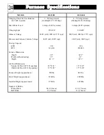
CLEARANCE REQUIREMENTS
The minimum clearances required when installing the furnace into
any area are as follows:
Back and Sides = 3 inches (from combustible material)
Top = 6 inches (from combustible material)
Front = 36 inches (for ease of servicing)
Furnace Right Side and Air Duct = 2 inches
Furnace Left Side and Air Duct = zero clearance
Sides of Furnace Ducts = zero clearance
The clearance areas must be kept open and free of debris. Do not
place anything on top the furnace. If the furnace is installed in a
small, enclosed area (less than 400 square feet), the area must be
well ventilated. For ventilation purposes, a minimum of a 24” X 24”
opening must be installed, if not already present, into the area where
the furnace is located. In addition, a 6” X 6” nonclosing type
register must be cut into the return air duct of the furnace to minimize
heat buildup in the room. (See Figure 3 for a depictition of clearance
specifications.)
3
FIGURE 3
FURNACE SET-UP
For cross reference to number coded components, see
the Exploded View Diagram and the Furnace Parts List
in this manual. Refer to Table 2 in the Shipping section
of this manual for a list of items each furnace should
contain.
Step 1
Unbox the brick storage cabinet
Step 2
Remove painted front panel (11) of cabinet by removing the sheet metal screws on the lower edge.
Rotate bottom edge of panel out to detach it from the cabinet.
Step 3
On the right side of the cabinet, remove the screws around the limit bar louvre panel (63). (See
Figure 4 for reference to the location of this panel and the screws.)
Step 4
Slide the sides and back painted outer panels (9,71, & 73) backwards as one assembly and remove
from cabinet.
Step 5
Use the handles on the brick storage cabinet to move it to its installation location. Set aside for now.
Removal of the limit switches (67) on the
right side of the brick storage cabinet
may be necessary to avoid damage to
these switches during the move.
Step 6
Remove the base assembly (50) from its box and move
it to the installation location. Discard the wooden
packaging from the top of the base. Locate and set
aside the hardware package shipped on top of the base
assembly.
Do NOT install the furnace on its
shipping pallet.
4
FIGURE 4
NOTE
NOTE
NOTE
Brick Storage
Cabinet
Содержание DLF30B
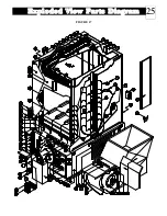
Страница 26: ...Exploded View Parts Diagram 25 FIGURE 17 ...


