-12-
ST1001 6" Jointer
Components and Hardware Needed:
Qty
Fence Assembly .................................................................... 1
Cap Screw M8-1.25 x 12 (Fence Assembly) ................ 2
Fence Cover ............................................................................ 1
Lock Handle (Fence Cover) ............................................... 1
Cap Screw M8-1.25 x 14 (Fence Cover) ........................ 1
Flat Washer 8mm (Lock Handle, Cap Screw) .............. 2
To install the fence:
1.
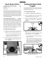
Lift the fence assembly onto the jointer table,
and attach the fence with the two M8-1.25 x 12
cap screws at the mounting locations shown in
Figure 13
.
Fence
Figure 13.
Fence installed on jointer.
Fence Mounting
Location
2.
Place the fence cover over the shaft at the rear
of the fence, and attach it to the fence with the
lock handle, cap screw, and flat washers shown
in
Figure 14
.
Figure 14.
Fence cover installed.
Lock
Handle
Cap Screw and
Flat Washer
11.
Attach the switch to the front of the jointer
with two Phillips head screws, flat washers, lock
washers, and hex nuts (see
Figure 12
).
Figure 12.
Switch installed.
Figure 11.
Belt cover installed.
Attach Cover Here
8.
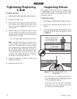
Push down on the motor to make sure the
weight of the motor tensions the V-belt.
9.
Tighten the motor mount hex nuts.
10.
Install the belt cover as shown in
Figure 11
.
Fence Cover
Belt Cover
Содержание ST1001
Страница 2: ......
Страница 36: ...34 ST1001 6 Jointer ST1001 Wiring Diagram...
Страница 37: ...ST1001 6 Jointer 35 Jointer Breakdown...
Страница 39: ...ST1001 6 Jointer 37 Fence Breakdown...
Страница 44: ......
Страница 47: ......
Страница 48: ......

