ST1001 6" Jointer
-11-
Components and Hardware Needed:
Qty
Motor ........................................................................................ 1
Motor Pulley ........................................................................... 1
Key (Motor Pulley) ................................................................ 1
Carriage Bolts
5
⁄
16
"-18 x 1
3
⁄
16
" (Motor) ........................... 4
Flat Washers
5
⁄
16
" (Motor) .................................................. 4
Lock Washers
5
⁄
16
" (Motor) ................................................ 4
Hex Nuts
5
⁄
16
"-18 (Motor) ................................................... 4
V-Belt ......................................................................................... 1
Belt Guard ............................................................................... 1
Phillips Head Screws M6-1 x 10 (Belt Guard) .............. 4
Lock Washers 6mm (Belt Guard) ..................................... 4
To install the motor:
1.
Place a piece of cardboard on the ground
approximately two feet away from the left side
of the jointer.
2.
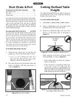
With the help of another person, carefully lay
the jointer on its left side, so the outfeed table
rests on the cardboard, as shown in
Figure 8
.
Motor
���
�������������
������������
�����
����������
������������
Figure 9.
Installing the motor pulley.
Figure 8.
Jointer on its side for motor installation.
4.
Place the motor on the motor mount bracket so
the motor shaft faces the rear of the jointer; and
attach the motor with the carriage bolts, flat and
lock washers, and hex nuts (
Figure 10
). Leave
the hex nuts loose enough so the motor can
slide up and down on the motor mount.
5.
Align the motor pulley with the cutterhead
pulley, and secure the motor pulley in place by
tightening the set screws shown in
Figure 9
.
6.
Install the V-belt on the pulleys.
7.
Pivot the jointer rightside up so it rests on all
four feet.
Figure 10.
Motor installed.
3.
Insert the key in the motor shaft keyway, and
slide the motor pulley onto the motor shaft
(
Figure 9
).
Содержание ST1001
Страница 2: ......
Страница 36: ...34 ST1001 6 Jointer ST1001 Wiring Diagram...
Страница 37: ...ST1001 6 Jointer 35 Jointer Breakdown...
Страница 39: ...ST1001 6 Jointer 37 Fence Breakdown...
Страница 44: ......
Страница 47: ......
Страница 48: ......

