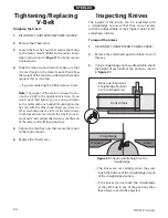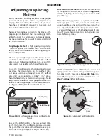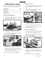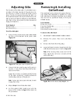
-32-
ST1001 6" Jointer
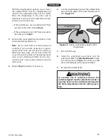
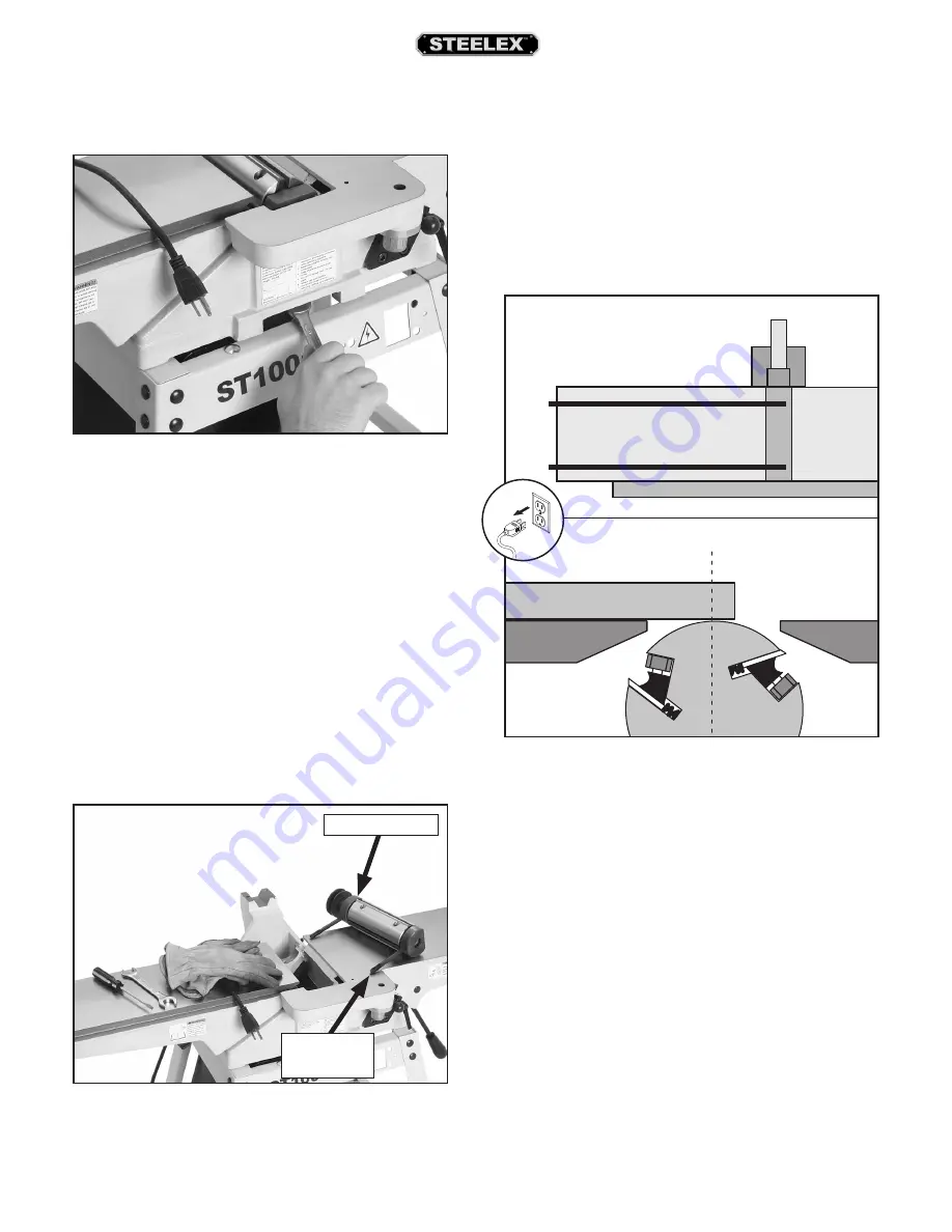
Figure 51.
Removing nut on bearing block stud.
5.
Remove the nut on the bearing block stud, as
shown in
Figure 51
, and repeat on the other
side.
6.
Wearing heavy leather gloves, carefully remove
the cutterhead from the casting (see
Figure
52
).
Note:
Your cutterhead may have paper shims
stuck to the bearing block or the part of the cast-
ing where the bearing block rests. These were
included at the factory when they calibrated your
cutterhead even with the outfeed table. If you see
these, carefully pull them off and set them aside
for later use, or keep them with your cutterhead
in the event that you reinstall it later. Also, mark
the side of the cutterhead where they were used,
so the future install will go smoothly. Your new
cutterhead may or may not need these.
To install the cutterhead:
1.
Place the cutterhead in position in the jointer.
2.
Secure the cutterhead in place with the hex
nuts.
3.
Using the straightedge and feeler gauge set,
inspect the cutterhead parallelism with the
outfeed table as shown in
Figure 54
.
Figure 52.
Cutterhead removed.
Bearing
Block Stud
Bearing Block
������������
�������������
Figure 54.
Checking cutterhead parallelism with a
straightedge (repeat at front/back of table).
���������������������
����������������������
������������������
�������������
Содержание ST1001
Страница 2: ......
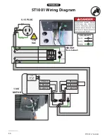
Страница 36: ...34 ST1001 6 Jointer ST1001 Wiring Diagram...
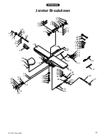
Страница 37: ...ST1001 6 Jointer 35 Jointer Breakdown...
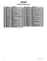
Страница 39: ...ST1001 6 Jointer 37 Fence Breakdown...
Страница 44: ......
Страница 47: ......
Страница 48: ......

