background image

O V E R V I E W  

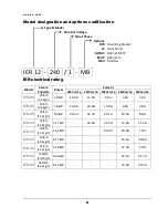
Model designation and options codification 


Type & Model  


Nominal Voltage 


Nb of Phase 


Options 


MB 

Mounting Bracket 


FS 

Floor Stand 


BC/MS 

BACnet MSTP 


BC/IP 

BACnet IP 


Mod 

Modbus  


IER  12  -  240  /  1  -  MB   


IER electrical rating 

Model 

Steam 

Capacity 

Power  

Current 

208Vac/1p  240Vac/1p  208Vac/3p  480Vac/3p  600Vac/3p 

IER-04 

10lb/h 

[4.5kg/h] 

3.3kW 

16.0A 

13.9A 

9.3A 

4.0A 

3.2A 

IER-05 

15lb/h 

[6.8kg/h] 

5.0kW 

24.0A 

20.8A 

13.9A 

6.0A 

4.8A 

IER-09 

24lb/h 

[11.4kg/h] 

8.3kW 

40.1A 

34.7A 

23.1A 

10.0A 

8.0A 

IER-12 

35lb/h 

[15.9kg/h] 

11.7kW 

44.2A 

32.4A 

14.0A 

11.2A 

IER-17 

50lb/h 

[22.7kg/h] 

16.7kW 

46.3A 

20.0A 

16.0 

IER-22 

65lb/h 

[29.5kg/h] 

21.7kW 

26.1A 

20.8A 

IER-31 

93lb/h 

[42.3kg/h] 

31.0kW 

37.3A 

29.8 

IER-44 

130lb/h 

[59.1kg/h] 

43.3kW 

52.1A 

41.7A 

IER-62 

185lb/h 

[84.1kg/h] 

61.7kW 

74.2A 

59.3A 


Содержание IER-04 Series

Страница 1: ...IVE STEAM HUMIDIFIER Installation and Operation Manual Please read and save this manual steamOvap technologies inc 9495 Charles de la Tour Montreal Qc H4N 1M5 Canada Tel 1 844 357 4477 www steamOvap com Rev 180401 IER ...

Страница 2: ......

Страница 3: ...e components must be done with original component and spare parts from steamOvap representative Installation and Operation Manual Limitation This IOM is intended for trained and qualified personnel and must be applied along with the applicable local codes and regulations Any work related to installation or service for this humidifier must comply with local code and regulation regarding safety and ...

Страница 4: ...Installation step 1 IER Positioning Mounting 12 Installation step 2 Water supply installation 18 Installation step 3 Drain installation 19 Installation step 4 Steam line installation 20 Installation step 5 Power supply installation 26 Installation step 6 Control installation 28 Verification before start up 30 Configuration Operation 32 Warranty 43 ...

Страница 5: ...garding safety and prevention of accidents Water safety warning Any work related to water supply drain connection as well as steam lines and condensate returns lines installation or service of such for this humidifier must comply with local code and regulation regarding safety and prevention of accidents Water supply connexion must be done by a trained and qualified plumber Risk of malfunction Ste...

Страница 6: ...rted as soon as possible to steamOvap or its representative and within 5 business days after receipt steamOvap will not assume any responsibility for missing item after this delay 4 Proceed carefully to unpacking and check that the humidifier and its accessories are not damaged in case of damage please proceed as for point 3 Included in standard delivery of IER electric steam humidifier 1 IER elec...

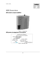
Страница 7: ...1 IER Overview IER product designation name plate steamOvap technologies inc Electric resistive steam humidifier MODEL IER12 240 1 S N YY DDDXXX POWER 12kW VOLTAGE 240Vac CURRENT 44 2A NB OF PHASE 1ph FREQUENCY 50 60Hz www steamOvap com Figure 2 IER Name plate section 2 ...

Страница 8: ...Vac 1p 208Vac 3p 480Vac 3p 600Vac 3p IER 04 10lb h 4 5kg h 3 3kW 16 0A 13 9A 9 3A 4 0A 3 2A IER 05 15lb h 6 8kg h 5 0kW 24 0A 20 8A 13 9A 6 0A 4 8A IER 09 24lb h 11 4kg h 8 3kW 40 1A 34 7A 23 1A 10 0A 8 0A IER 12 35lb h 15 9kg h 11 7kW 44 2A 32 4A 14 0A 11 2A IER 17 50lb h 22 7kg h 16 7kW 46 3A 20 0A 16 0 IER 22 65lb h 29 5kg h 21 7kW 26 1A 20 8A IER 31 93lb h 42 3kg h 31 0kW 37 3A 29 8 IER 44 130...

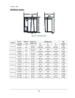
Страница 9: ...mm 23in 585mm 13in 330mm 55lb 25kg IER 12 35lb h 15 9kg h 1x medium 1x 2po DN50 23in 585mm 27in 686mm 17in 432mm 73lb 34kg IER 17 50lb h 22 7kg h 1x medium 1x 2po DN50 23in 585mm 27in 686mm 17in 432mm 73lb 34kg IER 22 65lb h 29 5kg h 1x medium 1x 2po DN50 23in 585mm 27in 686mm 17in 432mm 73lb 34kg IER 31 93lb h 42 3kg h 1x medium 1x 2po DN50 23in 585mm 27in 686mm 17in 432mm 73lb 34kg IER 44 130lb ...

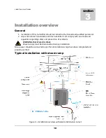
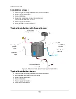
Страница 10: ...difier must comply with local code and regulation regarding safety and prevention of accidents WARNING Risk of electric shock Power supply must be disconnected during installation Main power should be connected only after all installation steps have been completed and properly verified Typical installation with steam ramp Figure 4 installation overview with steam distribution in duct section 3 ...

Страница 11: ... humidification in room 5 Power supply installation 6 Safety RH control installation Typical installation with Space blower Figure 5 IER with remote Space blower typical installation Typical installation steps 1 Positioning mounting of IER electric steam humidifier 2 Space blower installation only if remote 3 Water supply installation 4 Drain installation 5 Power supply installation 6 RH control i...

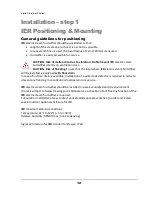
Страница 12: ...will be installed is equipped with floor drain In case of no floor drain is available installation of a water leak detector is required in order to prevent any flooding in case of abnormal operation or service IER electric steam humidifier should be installed in a well ventilated and dry environment If local is subject to below freezing point temperature activation of ant freezing function of the ...

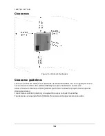
Страница 13: ...is a good practice to have a clearance of 4 to 8 in 100 to 200mm for ease of installation and service Allow a minimum clearance of 24in 610mm with floor to allow for proper drain slope and drain pipe column Front clearance of 30in 762mm is required for access to the IER humidifier Top clearance is required of 12in 304mm for access and proper steam connection ...

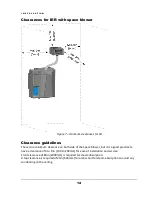
Страница 14: ...imum clearance on both side of the Space blower but it is a good practice to have a clearance of 4 to 8 in 100 to 200mm for ease of installation and service Front clearance of 80in 2000mm is required for steam absorption A top clearance is required of 24in 600mm for access and for steam absorption to avoid any condensing on the ceiling ...

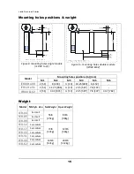
Страница 15: ...M5 M6 IER04 to 09 2 51 8 203 13 19 25 489 6 152 IER12 to 31 2 51 11 25 286 13 23 5 597 7 8 197 IER44 62 2 51 34 3 871 13 23 5 597 7 8 197 30 7 782 Weight Model Nb Cyl size Net Weight Oper Weight IER 04 1x small 55lb 25kg 84lb 38kg IER 05 1x small IER 09 1x small IER 12 1x medium 73lb 37kg 123lb 56kg IER 17 1x medium IER 22 1x medium IER 31 1x medium IER 44 2x medium 146lb 67kg 246lb 112kg IER 62 2...

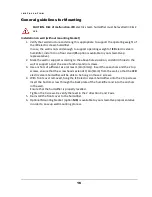
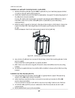
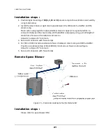
Страница 16: ...s to the wall or support as per the size of anchors and or screws 3 Use anchors of sufficient size at least 1 4in 6mm Insert those anchors and the 2 top screws ensure that the screw heads extends 1 4in 6mm from the wall so that the IER electric steam humidifier will be able to be hung on those 2 screws 4 With front cover removed hung the IER electric steam humidifier onto the 2 top screws Insert t...

Страница 17: ...g bracket is 15in 381mm Figure 10 Installation with Mounting bracket 4 Use anchors of sufficient size at least 1 4in 6mm Install the mounting bracket to the wall or support Ensure that the mounting bracket is properly levelled 5 With front cover removed hung the IER electric steam humidifier onto the mounting bracket 6 Install the 2 supplied screws to avoid the IER humidifier to move up from the m...

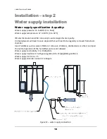
Страница 18: ... Untreated water will lead to scale deposits that will need to be regularly removed from steam chamber Use of additives such as scale inhibitor or corrosion inhibitors disinfectants or other can impair the normal operation of the humidifier and are not allowed Water supply conductivity 1 to 1500µS cm Water supply hardness 0 to 16grains gallon 0 to 15 gH 268mg CaCO3 l Water supply PH 6 5 to 7 5 Wat...

Страница 19: ... Water drained specification Drained water maximum temperature 120 F 60 C Drained water flow rate 6 6 GPM 25 l min Drain outlet dimension IER04 to 31 1x 1 1 4in 32mm IER44 62 2x 1 1 4in 32mm Figure 12 water drain connection Installation steps 1 Ensure that an Open drain with a P trap is installed offset from the IER humidifier IMPORTANT Risk of malfunction A minimum slope angle of 5 degree of the ...

Страница 20: ...0 Installation step 4 Steam line installation Duct humidification Horizontal duct Figure 13 SRS SRSX installation no dedicated condensate return line Figure 14 SRC SRCX installation with dedicated condensate return line to IER ...

Страница 21: ...n between the steam ramp IER humidifier and pipe by using a small length of steam hose for ease of installation and service Allow for a slope of 2 minimum 3 Secure all connexion with hose clamps 4 For SRC or SRCX install a condensate hose in between steam ramp and IER humidifier Provide a condensate trap of 8in 200mm minimum as shown on above figure Allow for a slope of 2 minimum 5 Secure all conn...

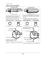
Страница 22: ...possible trouble due to condensate flow against the steam flow inside steam pipe or hose A condensate line must be installed and connected to drain or returned to humidifier Standard absorption Short absorption Standard absorption Short absorption Figure 17 SRS Figure 18 SRSX Figure 21 SRC Figure 22 SRCX Figure 19 SRS SRSX cover plate dimension Figure 23 SRC SRCX cover plate dimension Ø6in 152mm Ø...

Страница 23: ...ween top ramp and side wall of the duct d min ht min 4 5in 115min hb min There is no minimum height distance required for the bottom ramp 1 and the bottom of the duct However we recommend a minimum hb min 4in 100mm h min Height in between ramps h should be equal even h H ht hb nb of ramps 1 If ramps are aligned h min 8in 200mm Air flow can be one or the other direction If ramps are staggered h min...

Страница 24: ...between top ramp and side wall of the duct d min 4 5in 115min hb min There is no minimum height distance required for the bottom ramp 1 and the bottom of the duct However we recommend a minimum hb min 4in 100mm h min Height in between ramps h should be equal even h H ht hb nb of ramps 1 If ramps are aligned h min 8in 200mm Air flow can be one or the other direction If ramps are staggered h min 4 5...

Страница 25: ...O N 25 steamOsorb installation Figure 26 steamOsorb multiramp installation Figure 27 steam ramp profile and outlets position See detail drawing for complete dimensions And refer to steamOsorb IOM for installation steps Air ...

Страница 26: ...ly with local code and regulation regarding safety and prevention of accidents General guidelines for power supply installation Power supply wiring conductors must be copper only and rated for 105 C Refer to the above current rated to determine the appropriate wire sizes as well as conduit size and fused disconnect requirements The earth must be made by solid metal to metal connections Ground wire...

Страница 27: ...R 44 130lb h 59 1kg h 43 3kW 52 1A 41 7A IER 62 185lb h 84 1kg h 61 7kW 74 2A 59 3A Installation steps 1 Connect supply lines L1 L2 L3 and GND or L and N to the corresponding terminals in the IER electrical compartment Connect the earth conductor with a lug and secure it to the GND threaded stud 2 The supply wiring is to be fed into the unit via the clamp strap on the top of the unit 3 Ensure that...

Страница 28: ...point should be 85 RH minimum High limit humidistat should be placed at least at a distance equivalent to five times the absorption distance If the absorption distance is not known locate it at least 9 feet 3m downstream of the steam ramp For system that needs very accurate RH control a RH sensor can replace or supplement the On Off Hi Limit humidistat in this case the IER will not only modulate t...

Страница 29: ...l signal Dry contact Proportional RH or temperature sensor 0 10Vdc 2 10Vdc 4 20mA Installation steps 1 Ensure that the safety contact for Air proving switch and Hi limit humidistat are connected to the terminals 4 and 5 2 Connect the applicable controls according to the above wiring diagram 3 Selection of control signal is done through set up screens once the IER will be powered ...

Страница 30: ... of the steam distribution ramp Risk of freezing Plan an anti freeze system in case of installation in a location that would be exposed to outside conditions and susceptible of freezing Risk of malfunction Do not block steam outlet s Check list Mounting o Check mounting to verify that the IER is level and securely supported before filling with water Water supply o Verify that all piping connection...

Страница 31: ...sconnecting device with fuses is installed and easily accessible Control circuit o Verify that safety controls such as air proving switch and Hi limit humidistat have been connected o Verify that a control signal demand or RH sensor is connected to the control terminals Once all above verification has been completed and found satisfactory you can powered up the IER steam Humidifier ...

Страница 32: ...C O N F I G U R A T I O N O P E R A T I O N 32 Configuration Operation Dashboard screen Dashboard screen is also the main home screen Figure 31 Dashboard screen section 5 ...

Страница 33: ...O N F I G U R A T I O N O P E R A T I O N 33 Overview screen Overview screen gives all information on internal sensors and control settings and allow ordering a drain for service Figure 32 overview screen ...

Страница 34: ...s of enable button in Control setting control config ARMED_STATE IER is ready to operate waiting for humidity demand STEAM_ON_STATE IER is producing steam DRAINCYCLE_STATE IER is draining the cylinder ADD_WATER_STATE IER is adding water in the cylinder while producing steam or not PRE_HEAT_STATE If Preheat function is enable the IER is heating water in the cylinder ALARMS_STATE IER is on Alarm of ...

Страница 35: ...tting screen Control setting screen allows user control engineer to set signal and parameters to control the IER humidifier Access to this screen can be restricted with password In this case password is 3549 Pop up to enter password Figure 33 password screen ...

Страница 36: ...C O N F I G U R A T I O N O P E R A T I O N 36 Control setting control config Figure 34 Control setting control config screen ...

Страница 37: ...C O N F I G U R A T I O N O P E R A T I O N 37 Control setting setpoint output config Figure 35 Control setting setpoint config screen ...

Страница 38: ...C O N F I G U R A T I O N O P E R A T I O N 38 Control setting Hi Limit config Figure 36 Control setting Hi Limit config screen ...

Страница 39: ...etting screen Humidifier setting screen allows user mechanical contractor to set humidifier parameters Access to this screen can be restricted with password In this case password is 7030 Humidifier setting setting 1 Figure 37 Humidifier setting setting 1 screen ...

Страница 40: ...C O N F I G U R A T I O N O P E R A T I O N 40 Humidifier setting setting 2 Figure 38 Humidifier setting setting 2 screen ...

Страница 41: ...C O N F I G U R A T I O N O P E R A T I O N 41 Humidifier setting Main setting Figure 39 Humidifier setting setting 1 screen ...

Страница 42: ... Switch 1 latched Hi limit safety switch located on top of the cylinder is open Water level sensor def 1 Water level sensor is defective Water level sensor error 1 Water level detected is abnormal Water level too high 1 Water level is higher than expected Water level too low 2 Water level is lower than expected Water Temp Sensor def 1 latched Water temperature sensor is defective Water Temp Sensor...

Страница 43: ...until said products have been paid for in full and then said liability shall be limited to the original purchase price for the product Any further warranty must be in writing signed by an officer of steamOvap steamOvap makes no warranty and assumes no liability unless the equipment is installed in strict accordance with installation manual in effect at the date of purchase and by qualified and tra...

Страница 44: ...e la Tour Montreal Qc H4N 1M5 Canada Tel 1 844 357 4477 info steamOvap com www steamOvap com Information contained in this manual is subject to change without notice To obtain the latest technical information visit our website at www steamOvap com ...

Отзывы: