ENGLISH
12
12
- Never carry your power tool by its power cord.
- Keep the power cord away from heat, oil, solvents and
sharp edges.
- If the power cord becomes damaged have it replaced by
an authorized Stayer Iberica S. A service facility.
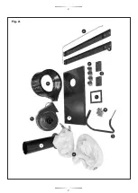
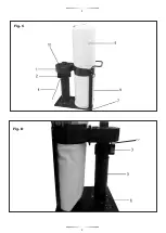
3.4 Illustrated description of parts.
1. - Collector body.
2. - Motor.
3. - ON / OFF.
4. - Power cable.
5. - Support the collector.
6. - Base of the machine.
7. - Wheels autogirables.
8. - Upper filter bag.
9. - Lower filter bag.
10. - Manifold cover.
11. - Reset button.
3.5 Limitations Environmental Conditions
Work Environment
- Do not expose your power tools to rain, or use in damp or
wet locations.
- Keep the work area well lit.
- Do not use power tools in areas where there is a risk of
explosion or fire from combustible materials, flammable
liquids, paint, varnish, petrol etc. flammable gases and
dust of an explosive nature.
3.6 List of contents
See index 1.
4. Operation Instructions
4.1 Placement and Testing
Do not use the power tool if the ON/OFF
(10)
switch does
not turn the power tool ON and OFF.
• Remove Adjusting Keys and Wrenches Form the habit of
always checking to see that keys and adjusting wrenches
are removed from the power tool before turning it on.
• Protect Furnishings. If using the power tool inside your
house protect furnishings and floors with a suitable dust
sheet.
• Use the right tool.
- Select the right tool for the job. Do not use a tool for a job
for which it was not designed.
- Do not force a small tool to do the job of a heavy-duty
tool.
- Do not use tools for purposes not intended; for example
do not use a circular saw to cut tree limbs or logs.
Do not attempt to modify the power tool in any
way.
- The use of any attachment or accessory other than those
recommended in this instruction manual could result in
damage to the power tool and injury to the operator.
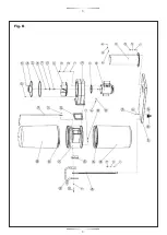
9.- Engine Board.
10.- Collector.
11.- Propeller-fan.
12.- Cotter C5x36.
13.- Fan Washer.
14.- M6x20 Hex.
15.- Air intake Board.
16.- Manifold cover.
17.- Screw M5x8 star.
18.- Support upper pouch.
19.- Screw M4x8 star.
20.- Collector output Board.
21.- Flat washer.
22.- Nut M8.
23.- Screw M6x16.
24.- Screw M5x8 star.
25.- Nut M6.
26.- Support wheel.
27.- Support base of the machine.
28.- Filter bag.
29.- Fixing clamp bag.
30.- Junction block supports.
31.- Link Collector bag.
32.- Carrying handle.
33.- Screw M8x45.
34.- Support bars.
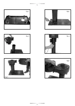
3.2.2. Assemblage Machine
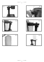
Fig 1:
Place the bracket over and install all four wheels
moving 4 screws with washer and nut on the 4 holes for
each wheel.
Fig 2:
Place the bracket and secure voice and present the
collector with 4 screws with washer and nut on the 4
corresponding holes .
Fig 3 and 4:
Support group in the upper engine manifold and
secure using the three star screws .
Fig 5 and 6:
Glue the gasket to the manifold outlet . Present
the manifold and secure the engine using the six screws
with washers .
Fig 7 and 8:
The assembly should be as in Figure 7. Install
the top tether strap bag with two Allen screws .
Fig 9:
Install the two brackets of the collector using a Phillips
screw down and two hex bolts and nut to fix up placing in
between the black plastic spacer block . Use the top of each
side hole for installing a carrying handle .
Fig 10 and 11:
Place the filter bag on each side presenting
the tightening strap on the collector pulling his tensioner
lever. Hang the bag tension wire top by stitching purpose.
Fig 12:
Connect the power plug to an outlet with regulatory
facility to include ground connection. The device is ready for
use.
3.3 Electrical connection icono
Connect the machine to a regulatory connection.
Make sure the connection is grounded and circuit breaker
30 mA.
Do not force the power tool. The power tool will do a better
and safer job and give you much better service if it is used at
the rate for which it was designed.
- Do not abuse the power cord
- Never yank or pull on the power cord to disconnect it from
the mains supply socket.
Содержание VAC70 B
Страница 2: ...4 6 8 12 1 2 3 7 11 5 9 Fig A 2 2 10...
Страница 3: ...Fig B 3 3...
Страница 4: ...Fig D 4 4 Fig C Fig D 11...
Страница 5: ...5 5 Fig 4 Fig 3 Fig 1 Fig 2 Fig 5 Fig 6...
Страница 6: ...6 6 Fig 9 Fig 10 Fig 12 Fig 11 Fig D Fig 7 Fig 8...


