7
EN
OPERATION
OPERATION
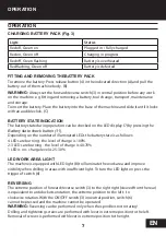
CHARGING BATTERY PACK (Fig. 3)
FITTING AND REMOVING THEBATTERY PACK
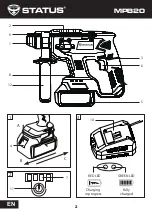
To remove the battery: Press release button (4) in the indicated direction (A) and pull the
battery out of the machine body. (B)
WARNING:
Always set the forward/reverse switch (3) in central position before any work
on the machine e. g. fitting and removing a battery, tool change, transport, maintenance
and storage.
To insert the battery: Place the battery into the base of the machine and slide it until it locks
with an audible click. (C)
BATTERY STATE INDICATION
The battery state during operation can be checked on the LED display (7) by pressing the
Battery state check button (11)
.
Depending on the number of illuminated LEDs the batterystate is as follows:
4 LEDs are burning - the level of charge is 100%.
2-3 LEDs are burning - the level of charge is 40-70%.
1 LED is on - charge level is 25-30%.
LED WORK AREA LIGHT
The machine is equipped with LED light (8) to illuminate the work area and improve
visibility when drilling in areas with insufficient light. To turn the LED light on press the
trigger of switch (6).
REVERSING
The extreme position of forward/reverse switch (3) to the right right (viewed from the rear)
is equivalent to anticlockwise rotation, the extreme position to the left - to
clockwise rotation. With the ON/OFF switch (3) in neutral position, switch (6)
cannot be pressed and the machine cannot be operated.
WARNING:
Reversing can be performed only when the spindle is not rotating!
Drilling and tightening screws are performed with lever in extreme position to the left.
Removal of screws is performed with lever in extreme position to the right.
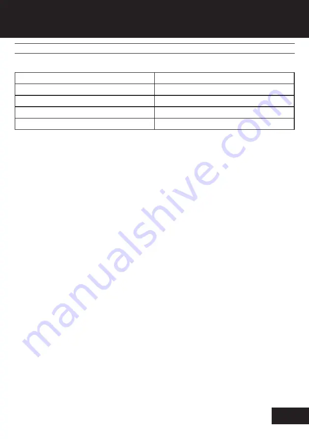
Ligts
Status
Red off, Green on
Plugged in / Fully charged
Red on, Green off
Charging in progress
Red off, Green flashing
Battery is overheated
Red flashing, Green off
Battery is defected


