Star SP712R series Скачать руководство пользователя страница 31

– 27 –

(3)  To adjust, use the FEED switch to select the adjustment pattern from the printout with the 

smallest gap between the first printing pass and the return printing pass. Press the FEED 

switch once to specify the first adjustment pattern, twice to specify the second adjustment 

pattern, and so on up to seven times to specify the seventh adjustment pattern.


At the number that you want to specify, press and hold (2 seconds) the FEED switch until 

the long buzzer sounds. This will specify the setting value. (For example, if you want to se-

lect the eighth pattern from the top, press the FEED switch seven times. Then, at the eighth 

pattern, press and hold (2 seconds) the FEED switch until the long buzzer sounds.)


There are only twenty three adjustment patterns. The buzzer will sound each time the FEED 

switch is pressed. However, if you press the FEED switch more than twenty three times, a 

warning alert will sound.

(4)  If there is no matching pattern among the adjustment patterns, perform the “Backward” or 

“Forward” operation described below in order to print a printing pattern in which the dot 

alignment settings are changed. Then, repeat step (3).

 Backward:

Press and hold the FEED switch for 2 to 4 seconds. The buzzer will beep, and the printer 

will print a pattern in which the forward is adjusted more leftward of the presently 

indicated pattern and the backward is adjusted more rightward.

 Forward:

Press and hold the FEED switch for 4 seconds or longer. The buzzer will beep-beep, 

and the printer will print a pattern in which the forward is adjusted more rightward 

of the presently indicated pattern and the backward is adjusted more leftward.

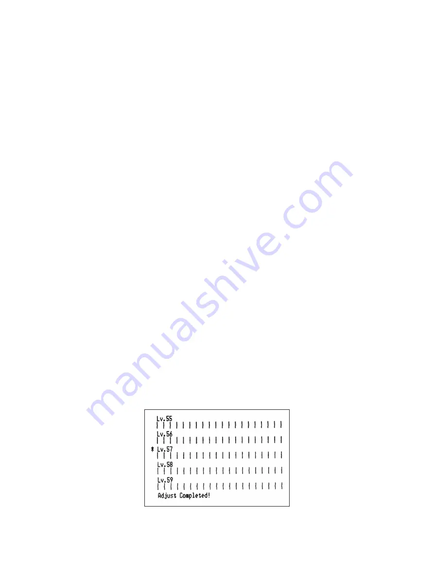
(5)  After selecting the adjustment pattern, the setting value is stored in the non-volatile memory. 

A printout similar to the one below with the selected adjustment pattern highlighted and 

the message “Adjust Completed!” will be printed.

 Note:  Before the printout is printed, the setting value is stored in the non-volatile memory 

of the printer after the adjustment pattern has been selected and the long buzzer 

sounds. During this period, do not set the power switch to off. If this power switch 

is set to off when the setting value is being stored in the non-volatile memory, the 

setting value for the adjustment pattern and all of the memory switch settings will 

be reset.

(6)  The long buzzer sounds once more and the setting value is automatically set.


The adjusting the dot alignment mode is complete.

Содержание SP712R series

Страница 1: ...DOT PRINTER SP712R 742R SERIES Paper Rewinder Model Hardware Manual...

Страница 2: ...e For RF interference suppression if a ferrite core is provided with this device affix it to the interface cable NOTE This equipment has been tested and found to comply with the limits for a Class A d...

Страница 3: ...nse Android is a trademark of Google Inc Windows is registered trademarks of Microsoft Corporation Copyright 2007 2017 Star Micronics Co Ltd Caution Symbol This symbol is placed near the print head to...

Страница 4: ...r Cord 11 4 5 Turning Power On 12 4 6 Installing the Cable 13 4 7 Switch Blind Installation 13 5 Loading the Ribbon Cartridge and Paper 14 5 1 Loading the Ribbon Cartridge 14 5 2 Loading the paper rol...

Страница 5: ...ment etc SP7 1 2 M D R Color None Standard color off white GRY Gray Rewinder None Without rewinder Standard R With rewinder Interface D Serial interface RS 232C C Parallel interface U USB E Ethernet W...

Страница 6: ...sheets Note Note The ferrite core and fastener provided with your printer depend on your printer configuration Fig 1 1 Unpacking If anything is missing contact the dealer where you bought the printer...

Страница 7: ...s and other sources of extreme heat 6 Do not locate the printer in a badly ventilated or dusty environment 7 Make sure that the room where you are using the printer is not too humid 8 This device empl...

Страница 8: ...pment but should be treated with a modicum of care in order to avoid malfunctions For example 1 Keep your printer in a comfortable environment Roughly speaking if you feel comfort able then the enviro...

Страница 9: ...Features one control switch and two indicators to indicate printer status Interface connector Connects the printer with host computer Power switch Turns printer power on and off Peripheral unit drive...

Страница 10: ...cable to a parallel port of your PC 4 1 2 RC 232 Interface Cable Connect the RC 232 interface cable to a RS 232 port of your PC 4 1 3 USB Interface Cable Connect the USB interface cable to a USB port...

Страница 11: ...make sure the power cable plug is disconnected from the AC outlet 4 2 1 Parallel Interface Cable 1 Make sure the printer is turn off 2 Affix the ferrite core onto the cable as shown in the illustrati...

Страница 12: ...the printer is turned off Also make sure the power cable plug is disconnected from the AC outlet 2 Connect the interface cable to the connector on the rear panel of the printer 3 Tighten the connector...

Страница 13: ...not included perform steps 1 and 5 only 5 Connect the interface cable to the connector on the rear panel of the printer Link disconnection detection feature The Ethernet interface model is equipped w...

Страница 14: ...is turned off and unplugged from the AC outlet and that the computer is turned off before making connections 1 Connect the peripheral drive cable to the connector on the rear panel of the printer CAU...

Страница 15: ...voltage matches that of the AC outlet Also make sure the plug on the power cord matches the AC outlet 2 If the power cord is not attached to the printer plug the appropriate end into the AC inlet on t...

Страница 16: ...recommend that you unplug the printer from the power outlet whenever you do not plan to use it for long periods Because of this you should locate the printer so that the power outlet it is plugged int...

Страница 17: ...ated by mistake Ensuring that other people can not easily operate the power switch Install the switch blind as shown in the diagram below The power switch can be turned ON and OFF O by inserting a nar...

Страница 18: ...hould you not put your hand in the paper outlet slot while printing is in progress never put your hand into the outlet even when printing is not in progress 3 Place the ribbon cartridge in the directi...

Страница 19: ...be extremely hot On the auto cutter model there is a paper cutter at the paper outlet slot Never allow your hand to come in contact with the cutter blade 2 Load the paper roll in the direction as show...

Страница 20: ...the slit 6 Wind the paper roll twice around the spool Note Wind the paper roll without loosening it while the right end of the paper roll is in contact with the spool rim 7 As you load the spool onto...

Страница 21: ...nter cover 0 Cut the leading edge of the roll paper as shown Note When the paper end mark appears on the reverse of the paper replace the paper roll before it runs out Opening the printer cover before...

Страница 22: ...the attached roll paper guide in the groove in the printer The setting for memory switch 2 A and 2 B must be changed to change the print width For instructions on setting the memory switch please refe...

Страница 23: ...moke a strange odor or unu sual noise Immediately unplug the equipment and contact your dealer for advice P Never attempt to repair this product yourself Improper repair work can be dangerous P Never...

Страница 24: ...purposes do not connect wiring to the external drive connector if there is a chance it may carry peripheral voltage P Donotoperatethecoveropenleverwhilepressingontheprintercoverwithyourhand P Donotpu...

Страница 25: ...D 1 POWER lamp Green LED 1POWER lamp Green LED Lights when the power is ON 2FEED button Press the FEED button to feed roll paper 3ERROR lamp Red LED Indicates various errors in combination with POWER...

Страница 26: ...On Flashes On 0 25sec Off 0 25 sec 2shortbeeps 0 13sec 0 5 sec 7 Blackmarkdetectionerror On Flashes On 0 5 sec Off 0 5 sec 3shortbeeps 0 13sec 0 13sec 0 13sec 8 Link disconnection detec tion Physical...

Страница 27: ...the error occurs STAR Mode Non recoverable error ESC POS Mode Recoverable error 8 For paper jam errors Clear the jammed paper and change the paper roll if necessary For incorrect paper format errors...

Страница 28: ...olding down for 2 more seconds 4 The Black Mark Sensor Alignment Mode is entered by releasing the FEED switch after the buzzer sounds four times Refer to Section 6 4 4 Holding down for 2 more seconds...

Страница 29: ...performed to print the Ver No and printer settings ASCII printing will be repeatedwhentheFEEDswitchisheldcontinuouslyattheendofASCII printing Theself printing mode will end automatically when the FEE...

Страница 30: ...he following This is caused when mechanical parts of the printer get out of alignment This happens only rarely and you may never experience it at all throughout the life of the printer If you do have...

Страница 31: ...s are changed Then repeat step 3 Backward PressandholdtheFEEDswitchfor2to4seconds Thebuzzerwillbeep andtheprinter will print a pattern in which the forward is adjusted more leftward of the presently i...

Страница 32: ...function allows you to check if a control code sent to the printer by the program being used is correct or not The last line is not printed if its data is less than one full line However if the FEED s...

Страница 33: ...ced upright Therefore secure the printer by placing your hand on the printer before performing this operation 8 1 Power OFF VR2 VR1 3 Since it is adjusted by rotating the volume VR2 check the position...

Страница 34: ...uto cutter to the home posi tion by following the instructions provided in Section 7 3 3 Remove the jammed paper CAUTION Take care not to damage the printer when removing the jammed paper 4 Position t...

Страница 35: ...s not recovered proceed to step 3 3 Pull the cover open lever towards you open the printer cover and close the platen arm The printer cover may not open due to the cutter being locked In this case fol...

Страница 36: ...er is locked insert a Phillips screwdriver into the Phillips screw hole on the side of the cutter and turn it in the direction of the arrow shown below in order to return the cutter to its normal posi...

Страница 37: ...URL http www star m jp eng Rev 1 3...

Отзывы: