background image

40 


620-7925 Rev x1 


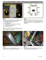
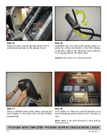
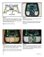
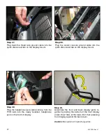
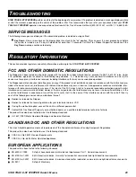
Step 9.  

Remove  the  cap  cover  with  the  Star  Trac  logo 
from the back cover plastics by removing the (2) 
screws  using  a  #2  Phillips  screwdriver.  Retain  
screws for later use. 
 

Note: 

You will no longer need the cap cover and, if 

desired, you can store it away for any possible future 
use. 

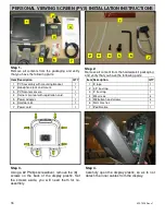
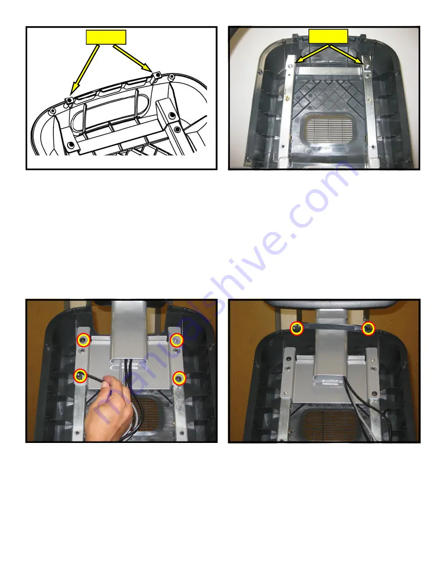
Step 10.  

Remove  the  (2)  M8  buttonhead  screws  retain-
ing  the  cross-brace  using  provided  5mm  Hex 
key.  Retain screws for later use. 
 

Note:

 You will no longer need the cross-brace and, 

if desired, you can store it away for any possible fu-
ture use. 

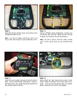
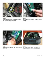
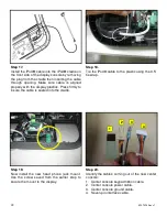
Step 11.  

Mount the PVS assembly on the mounting 
bracket, then thread the (4) M8 button Head 
screws through the PVS mounting bracket into 
the display mount.  Do not tighten the screws 
yet. 
   

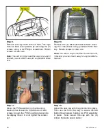
Step 12. 

Adjust the new cap with the grommet into place.  
Then  use  the  5mm  Hex  key  to  secure  the  M8 
Button Head screws holding the PVS assembly 
in  place.    Now  secure  the  cap  with  the  (2) 
screws that were saved earlier. 

Screws 

Screws 

Содержание E-STe

Страница 1: ...2 620 7925 Rev x1 STAR TRAC 14410 Myford Road Irvine CA 926060 USA WORK INSTRUCTIONS E ST E STe INSTALLATION...

Страница 2: ...ist is completed on each Star Trac product Complete the final programming functional and cosmetic checklists for each Star Trac product FACTORY CERTIFIED INSTALLER Copyright 2008 Star Trac by Unisen I...

Страница 3: ...embled Cut and remove packaging straps Step 2 Lift and remove the top box off the pallet base Step 3 Remove the handrail box from the shipping pal let and place aside Step 4 Carefully remove the displ...

Страница 4: ...ew Neck Joint 4 Step 5 Lift the unit off of the pallet base and place it on the floor Step 8 Place all components on the floor then verify all items are accounted for and that no visual dam age is pre...

Страница 5: ...hrough the upper neck Caution Take care not to damage the display plas tics or handlebar on the ground Step 4 Keep hold of the cables and rotate the display up Now slide the neck over the two mounts i...

Страница 6: ...8 Button Head Screws into the upper handrail Then tighten each screw to 110 lb in 12 4 N m of torque Repeat for the other handrail Step 8 Thread 2 1 4 28 x 3 8 Button Head Screws into the lower handr...

Страница 7: ...ith Personal View ing Screen the coax and DC power cables should be tucked down the neck as they are part of the PVS Kit Step 11 Plug in the 12 pin main I O cable into the front display circuit board...

Страница 8: ...ug the HR ground cable into the quick discon nect tab on the display frame Step 15 Place the stepper on the floor in the position it will be used Then adjust leveling feet to as sure that the stepper...

Страница 9: ...proper installation of the E Series Stepper 1 All parts and hardware in the package are accounted for 2 All screws are tightened down to their specified values 3 Upper neck is properly mounted and se...

Страница 10: ...11 620 7925 Rev x1 THIS PAGE INTENTIONALLY LEFT BLANK...

Страница 11: ...th the display and place it face down on top of a non scratching surface to protect it from being damaged Step 4 Remove the back cover from the embedded dis play assembly and place it in a safe place...

Страница 12: ...able for later use Step 6 Mount the back cover to the display mounting bracket using 4 M4 x 0 7 x 19mm long Phillips head screws and four 4 M4 flat washers Step 7 Attach the ground cable to upper left...

Страница 13: ...y plastics at the top with one hand while connecting the cables and harnesses with the other Step 11 Identify the four cables coming out of the neck and mounting bracket 1 Heart rate cable 2 Main I O...

Страница 14: ...Now plug in the DC power cable from the base neck into the DC connectors on the embedded display assembly Step 13 Plug in the 12 pin main I O cable from the neck into the 12 pin connector on the FitC...

Страница 15: ...into the quick disconnect tab on the embedded display assembly 1 2 Step 19 Connect the in house entertainment cable to the RF input at the base of the unit Next take the power supply from the kit and...

Страница 16: ...age are accounted for 2 Embedded display assembly is clear of any scratches or damage 3 The front and back display plastics are properly installed and secured 4 All screws are tightened down to their...

Страница 17: ...18 620 7925 Rev x1 THIS PAGE INTENTIONALLY LEFT BLANK...

Страница 18: ...tallation prior to mounting the display assembly onto the frame Step 3 Using a 2 Phillips screwdriver remove the 8 screws on the back of the display plastic Set the screws aside you will need them for...

Страница 19: ...rd and the display mount Step 6 Disconnect the 12 pin serial connector from the display Step 7 Now disconnect the heart rate connector from the display Step 8 Be careful with the display and place it...

Страница 20: ...will no longer need those covers and they can be stored away for any possible future use Step 11 Using a Phillips head screwdriver remove the 4 screws that hold the original center console in place th...

Страница 21: ...y the cables coming out of the new center console 1 Center console keypad ribbon cable 2 Headphone jack cable 3 Center console ground cable 4 Seven pin interface cable Step 15 Connect the center conso...

Страница 22: ...ttach the male 12 pin connector to the fe male 12 pin connector on the display board Then connect the 2 DC power connectors to the center console Note The DC power cables can be plugged to ei ther one...

Страница 23: ...console to the base unit Hold the front dis play plastics at the top with one hand while con necting the cables and harnesses with the other Step 22 Connect the CSAFE power cable from the bot tom cove...

Страница 24: ...Step 27 Plug back the Heart rate ground cable into the quick disconnect tab on the display mount Step 26 Next plug in the heart rate cable from the neck into the heart rate board connector on the dis...

Страница 25: ...cover Caution Be careful not to pinch any wires Step 30 Using a Phillips head screw driver secure the front display to the back with 8 M4 Phillips head screws Step 31 Turn power on Perform a visual in...

Страница 26: ...s Use the checklist below to ensure the proper installation of the iPod Kit on the E Stepper 1 All parts tools and hardware in the package are accounted for 2 Center console assembly is properly mount...

Страница 27: ...28 620 7925 Rev x1 THIS PAGE INTENTIONALLY LEFT BLANK...

Страница 28: ...unit then perform this installation prior to mounting the display assembly onto the frame Step 2 Using a 2 Phillips screwdriver remove the 8 screws on the back of the display plastic Set the screws as...

Страница 29: ...display Step 7 Be careful with the display and place it face down on top of a non scratching surface to pro tect it from being damaged Step 8 Using a 2 Phillips head screwdriver remove the 4 screws th...

Страница 30: ...in place then remove the center console Note You will no longer need the center console and it can be stored away for any possible future use Step 11 Insert the new center console into the front dis p...

Страница 31: ...ground cable 4 Seven pin interface cable Step 14 Connect the center console keypad cable to J8 connector on the display board Step 15 Connect the seven pin interface cable from the console to J14 conn...

Страница 32: ...splay use the screws saved from the earlier step to secure the display bottom Tighten the screws so they are snug then plug in the CSAFE power cable into the back of the display Note Take special care...

Страница 33: ...are part of the PVS and embedded kits and should be tucked down the neck for possible future use 1 2 3 4 Step 22 Plug in the 12 pin main I O cable from the neck into the new 12 pin adaptor Step 23 Ne...

Страница 34: ...rst then pressing front display against the back cover Caution Be careful not to pinch any wires Step 27 Using a Phillips head screw driver secure the front display to the back with 8 M4 Phillips head...

Страница 35: ...ensure the proper installation of the iPod Kit on the E Stepper 1 All parts tools and hardware in the package are accounted for 2 Center console assembly is properly mounted and secured 3 All screws a...

Страница 36: ...37 620 7925 Rev x1 THIS PAGE INTENTIONALLY LEFT BLANK...

Страница 37: ...om the display PERSONAL VIEWING SCREEN PVS INSTALLATION INSTRUCTIONS Step 2 Remove all content from the hardware kit packaging and verify that you have the following parts 1 2 3 4 5 6 7 Item Descripti...

Страница 38: ...e heart rate board and the display mount Step 6 Disconnect the 12 pin serial connector from the display Step 7 Now disconnect the heart rate connector from the display Step 8 Be careful with the displ...

Страница 39: ...provided 5mm Hex key Retain screws for later use Note You will no longer need the cross brace and if desired you can store it away for any possible fu ture use Step 11 Mount the PVS assembly on the m...

Страница 40: ...no longer need the headphone jack cover and it can be stored away for any possible future use Step 15 Using a Phillips head screwdriver remove the 4 screws that hold the original center console in pl...

Страница 41: ...s Press firmly to insure the cable is seated into the cradle Step 19 Now install the new head phone jack mount Use the screw saved from the earlier step to secure the mount to the display Step 20 Iden...

Страница 42: ...the center console board Step 24 Next replace the bottom cover Use the screws saved from the earlier step to secure the display bottom Tighten the screws so they are snug then plug in the CSAFE power...

Страница 43: ...jack cable 3 DC power cable 4 Data interface cable 5 Video cable 6 Audio cable Step 28 Connect the coax cable coming out of the base unit with the coax cable coming out of PVS neck Secure tightly 1 2...

Страница 44: ...p from the PVS kit bind the cables from the PVS neck to one side of the display mount Take the tie and put it through the hole on one of the display mount tubes Step 31 Plug in the 12 pin main I O cab...

Страница 45: ...power cable from the PVS neck into the other DC con nectors on same center console board Step 34 Plug the data interface cable coming from the PVS neck into the center console board Step 35 Plug the...

Страница 46: ...tab on the display mount Step 39 Plug the headphone jack cable coming from the PVS neck into the newly installed headphone jack on the front of display Step 40 Assemble the front and back display part...

Страница 47: ...rom the kit and plug it into the power supply and the electrical receptacle Step 43 Turn power on Perform a visual inspection and test the features and functions of the unit prior to use Note Refer to...

Страница 48: ...ckage are accounted for 2 Personal Viewing Screen assembly is properly mounted and secured 3 Center console assembly is properly mounted and secured 4 All screws are tightened down to their specified...

Страница 49: ...50 620 7925 Rev x1 STAR TRAC 14410 Myford Road Irvine California 92606 Telephone 800 228 6635 714 669 1660 Fax 714 508 3303 http www startrac com...

Страница 50: ...Star Trac E ST Stepper O W N E R S M A N U A L...

Страница 51: ...ly in incre ments of 1 unit These keys do not save the new value see OK Key below Numeric Keypad Allows you to enter specific values for numeric parameters These keys do not save the new value see OK...

Страница 52: ...since last reset Manual 0 65535 0 Number of times the Manual program was run since last reset Fat Burner 0 65335 0 Number of times the Fat Burner program was run since last reset IHR Prog 0 65535 0 Nu...

Страница 53: ...p This product has also been tested to meet the following standards I UL 1647 1997 Motor Operated Massage and Exercise Machines CANADIAN DOC AND OTHER REGULATIONS This class A digital apparatus meets...

Отзывы: