


24
620-7925 Rev x1
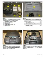
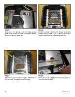
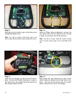
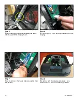
Step 21.
Install the new bottom plastic cover onto display,
use the screws saved from the earlier step to
secure the display bottom. Tighten the screws
so they are snug.
Note:
Take special care to not pinch any of the ca-
bles between the plastics.
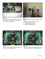
Step 23.
Take the front display plastics with the new cen-
ter console to the base unit. Hold the front dis-
play plastics at the top with one hand while con-
necting the cables and harnesses with the
other.
Step 22.
Connect the CSAFE power cable from the bot-
tom cover to J10 connector on the display
board.
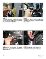
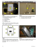
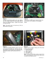
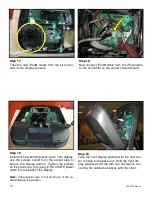
Step 24.
Identify the four cables coming out of the neck
and mounting bracket:
1. Heart rate cable
2. Main I/O cable
3. Coax cable
4. DC power cable
Note:
The coax and DC power cables are part of the
PVS and embedded kits and should be tucked down
the neck for possible future use.
1
2
3
4
Содержание E-STe
Страница 10: ...11 620 7925 Rev x1 THIS PAGE INTENTIONALLY LEFT BLANK...
Страница 17: ...18 620 7925 Rev x1 THIS PAGE INTENTIONALLY LEFT BLANK...
Страница 27: ...28 620 7925 Rev x1 THIS PAGE INTENTIONALLY LEFT BLANK...
Страница 36: ...37 620 7925 Rev x1 THIS PAGE INTENTIONALLY LEFT BLANK...
Страница 50: ...Star Trac E ST Stepper O W N E R S M A N U A L...


