background image

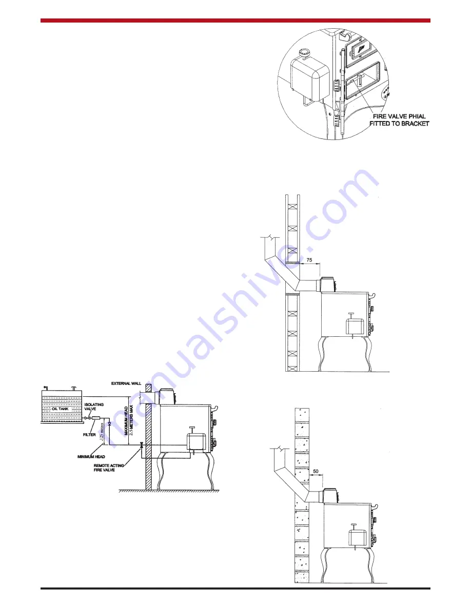
An oil filter (5 - 10 micron) and stop valve must be fit-
ted to the fuel feed line and located near the supply
tank and facilities should be provided to enable it to
be serviced without draining down the oil supply sys-
tem. (See fig.4).

At the point where the oil line enters the building, the
oil line must be fitted with an approved remote act-
ing fire valve which meets the requirements of B.S.
5410 : Part 1, fitted with the appropriate length of
capillary.  The temperature rating limit should be
90

o

C.  The heat sensoring phial of the fire valve

should be passed through the base of the burner
compartment and fitted through the fire valve brack-
et provided in the burner compartment (see Fig.5).  It
is absolutely essential that the fire valve is located
externally and is as close as possible to the appli-
ance.  For existing installations where the oil supply
is built into the structure internally, the remote acting
fire valve should be fitted where the oil supply line is
first exposed internally.  This type of layout is not
recommended for new installations.

These requirements are further explained within the
following documents: 
*

BS 5410: Part :  Code of practice for Oil
Firing installations up to 45 kW output 
capacity for space heating and hot water 
supply purposes.

*

OFTEC Technical Information Book Three: 
Installation Requirement for Oil Fired Boilers
and Oil Storage Tanks.

*

The Building Regulations Part J:  England
Wales, Part F - Section 4 Scotland and Part
L Northern Ireland.

CLEARANCES TO COMBUSTIBLES

The minimum clearance to combustible materials
should be maintained at least 75mm (3”) from rear of
cooker (see Fig. 6).

Fig.4

Fig.5

6

Fig.6

The minimum clearance to non-combustible materi-
als should be maintained at least 50mm (2”) from
rear.  (see Fig.7)

If there are other oil fired appliances connected to
the oil storage tank especially appliances with oil
pumps e.g. oil fired boilers or stoves, it is recom-
mended that a separate oil supply line is taken from
the oil tank to the cooker.  The separate oil supply
line to the cooker will avoid the possibility of the
pumped appliance taking oil from the cooker burner.
A suitable shut off valve should be fitted near the
cooker and be accessible at all times.

NOTE:

Ensure that the fire valve phial is not touch-

ing any point of the base casting.

Fig.7

Содержание DHW

Страница 1: ...ERRIGAL OIL FIRED COOKER DRY DHW HPB MODELS INSTALLATION OPERATING INSTRUCTIONS ...

Страница 2: ...n Draughts 9 22 Factory Made Insulated Chimneys 9 23 Suitable Materials 9 24 Heating 10 25 Safety Valve 10 26 Pipe Fittings 10 27 Indirect Domestic Cylinder 10 28 Direct Domestic Cylinder 10 29 Interlink System 11 30 General Maintenance 11 31 Draining 11 32 Pre Installation Assembly 11 33 Fitting of Legs 11 34 Commissioning 13 35 Burner Set up 13 36 Burner Assembly 14 37 Flame Pattern 15 38 Cooker...

Страница 3: ...rseded during the life of this manual 1 Burner Compartment 2 Air Intake Spin Valve 3 Burner Viewing Glass 4 Hot Plate 5 Chimney Damper 6 Fire Valve Phial 7 Oven Door 8 Cleaning Door 9 Hob 10 Bonnet Door 11 Spin Valve 12 Oil Control Valve 13 Oil Control Valve Cover 14 Fire Valve Bracket IMPORTANT CONTROL OF SUBSTANCES HARMFUL TO HEALTH It is the users installer responsibility to ensure that the nec...

Страница 4: ...RE OF BOILER 40 PSI 2 75 Bar OPERATING TEMPERATURE LIMIT 960 C 205O F BOILER CAPACITY WHERE APPLICABLE 7 5 Litres HPB or 5 5 Litres DHW COOKER WEIGHT 232 Kgs 510 lbs SPACE HEATING 3 kW s 10 000 Btu s Valve Setting Oil Consumption Burner Input Oven Temperature Heat Output to Water 1 h kW Btu hr oC kW Btu hr 6 1 14 13 38 45 690 225 5 86 20 000 5 0 98 11 51 39 300 210 4 54 15 500 4 0 83 9 74 33 270 1...

Страница 5: ...II Scotland Part L Northern Ireland Part J Ireland The Control of Pollution Oil Regulations B S 5449 Forced Circulation Hot Water Central Heating System for Domestic Installation Safety Health and Welfare at Work Act for Ireland England Wales Scotland B S 7593 Treatment of Water in Domestic Hot Water Systems B S 7074 Part 1 2 Hot Water Supply B S 4814 Sealed Systems 4 NOTE These times may differ s...

Страница 6: ...ble pipe with a minimum internal diameter of 8mm 5 16 and connected to the oil control valve Supply pipes are normally run in annealed copper tube complying to EN 1057 It can be obtained in coil or half hard form for use with bending machines This pipe can also be obtained with protective plas tic sheathing applied Fittings for copper pipe should be compression of the flared manipulative type to B...

Страница 7: ...allations These requirements are further explained within the following documents BS 5410 Part Code of practice for Oil Firing installations up to 45 kW output capacity for space heating and hot water supply purposes OFTEC Technical Information Book Three Installation Requirement for Oil Fired Boilers and Oil Storage Tanks The Building Regulations Part J England Wales Part F Section 4 Scotland and...

Страница 8: ...ting flue pipe or chimney that has proved to be satisfactory when used for solid fuel can normal ly be used for this appliance provided that its con struction condition and dimensions are acceptable Flues that have proven to be unsatisfactory particu larly with regard to down draught must not be con sidered for venting this appliance until they have been examined and any faults corrected If there ...

Страница 9: ...r closure The effective free area of any vent should be ascertained before installation The effect of any grills should be allowed for when determining the effective free area of any vent Air vents direct to the outside of the building should be located so that any air current produced will not pass through normally occupied areas of the room An air vent outside the building should not be locat ed...

Страница 10: ...used will not restrict the flue exit or cause excessive back pres sure Fig 10 FACTORY MADE INSULATED CHIMNEYS Factory made insulated chimneys should be con structed and tested to meet the relevant standards and recommendations given in B S 7566 Installation of factory made chimneys conforming to B S 4543 for domestic appliances Part 1 Method of specifying installations design information Part 2 Sp...

Страница 11: ...installation work should be resis tant sound and should conform to the current edi tions of the following or their equivalent 1 1 Ferrous Materials BS 4127 Stainless steel tubes BS 1387 Steel tubes BS 1740 Steel pipe fittings BS 6956 Jointing Materials 1 2 Non Ferrous Materials EN 29453 Soft Solder Alloys BS 864 Compression tube fittings BS 2871 BS E N 1057 Copper and Copper Alloys INDIRECT DOMEST...

Страница 12: ... running costs while equally enhancing living condi tions DRAINING Key operated drain taps conforming to B S 2879 should be provided in an accessible position in all low parts of the system However it should be noted that there may be short sections e g when passing under doorways that may not be possible to drain PRE INSTALLATION ASSEMBLY 1 Remove packing strip from the top of cooker Remove all l...

Страница 13: ...net when in place with cement Depending on the flue configuration required top or back the blanking plate is fitted to the top or back of the bonnet See Fig 19 12 Fig 17 Fig 18 7 Bolt the float valve bracket to the underside of the base using the two 1 2 x 1 4 round head screws provided See Fig 18 8 Connect the formed fuel line to the control valve outlet and the elbow connection in the burner com...

Страница 14: ...after 5 minutes it may be neces sary to bleed the oil line at the elbow con nector in the burner compartment 4 Check the oil in the burner rings The oil level should be 4mm See Fig 23 If the level is greater than required the control valve should be lowered The control valve bracket can be moved up and down by loos ening the M4 lock nuts If the level is less than required the control valve should ...

Страница 15: ...ED DOWN SEE FIG 24 BURNER ASSEMBLY With the burner level and the correct depth of oil in the burner rings the following tips should be fol lowed for assembling the burner 1 Replace the wicks in the burner rings Ensure that the cut outs in the wicks line up with the fuel ports between the central reser voir and the burner rings See Fig 27 2 Replace the cast iron centre well cap grind ing it into po...

Страница 16: ...tain flue buoyancy 15 Fig 30 ALWAYS OPEN THE DIRECT FLUE DAMPER BEFORE LIGHTING THE COOKER NEVER RE LIGHT THE COOKER UNTIL IT IS COMPLETELY COOLED DOWN SEE FIG 24 Note The angle on the DHW Dry baffle is directed towards the oven See Fig 29 DHW AND DRY HPB Fig 28 6 Place the air distribution baffle in the burner compartment ensuring that it sits on top of the carbon leg assembly fuel line Ensure th...

Страница 17: ... substantial soot build up the flue may need to be cleaned 8 Replace the burner in the firebox and recon nect the oil line to the burner 9 Check that the burner and oil control valve are level in all directions Check all oil con nections to ensure that there are no leaks See Fig 33 10 Turn the control valve to 6 to fill the burner Check that the correct level of oil is present See Commissioning Se...

Страница 18: ...l falls into the vessel 3 Measure the oil flow for 5 minutes consult table below for current rate 4 Turn the control valve to 1 and repeat the above procedure 5 If either of the above rates is not correct the control valve can be adjusted The high rate screw is located above the control knob with the low rate located below the control knob See Fig 35 The screws are very sensitive and the measureme...

Страница 19: ...lve Cover 37 Control Knob 38 Oil Control Valve 39 1 4 x 8mm Compression Fitting 40 Ashpit R H S 41 Flue Check 42 Grate Support Frame 43 Oven Back 44 Flue Back 45 LH Oven Side 46 Back Sealing Plate 47 Small Back Panel 48 Oven Top 49 Direct Damper 50 Ashpit Back 51 R H Window Frame 52 Viewing Glass Frame 53 Viewing Glass 54 L H Window Frame 55 S90 Boiler 56 Hob 57 Hob Rod Caps 58 Simmering Plate 59 ...

Страница 20: ...7 Control Knob 38 Oil Control Valve 39 1 4 x 8mm Compression Fitting 40 Ashpit R H S 41 Flue Check 42 Grate Support Frame 43 Oven Back 44 Flue Back 45 L H Oven Side 46 Back Sealing Plate 47 Small Back Panel 48 Oven Top 49 Direct Damper 50 Ashpit Back 51 R H Window Frame 52 Viewing Glass Frame 53 Viewing Glass 54 L H Window Frame 55 Superette Boiler 56 Hob 57 Hob Rod Caps 58 Simmering Plate 59 Flue...

Страница 21: ...ow Frame 55 Sham Cheek 56 Hob 57 Hob Rod Caps 58 Simmering Plate 59 Flue Deflector Plate 60 Hotplate 61 Bonnet Spin Valve 62 Bonnet Door 63 Bonnet 64 Back Outlet Adapter 65 Bonnet Blanking Plate 66 Bonnet Top Spigot 67 RHS Back Fire Brick S90 No 2 68 Back Panel 69 Cleaning Cup 70 Burner Stand 71 1 4 x 8mm Compression Elbow 72 Burner Pot Elbow Adapter 73 Carton Leg Assembly 74 Bonnet Gasket 75 Cent...

Страница 22: ... control valve fuel input rate Dirty or Unstable Flame Viewing Incorrect Chimney Draught Check joint seals increase Glass sooting up Chimney height adjust flue bonnet spin valve Incorrect Fuel Input Rate Check Fuel Input Rate adjust if necessary Incorrect Spin Valve Setting Adjust Spin Valve Setting Shells or Vapour Chamber Lid Ensure all shells are seated not seated properly on Burner base and th...

Страница 23: ...s described in the Clearance to Combustibles Section 2 The cooker should be installed as to allow adequate air circulation around the cooker and to allow access for installation servicing 3 The cooker must be installed on a non combustible insulated floor protector that covers the area under the cooker and extends 6 from the side and back and 9 from the front of the cooker Plumbing Boiler Models O...

Страница 24: ...Rev 006 DP 070126 N00184AXX 23 Manufactured by Waterford Stanley Ltd Unit 210 IDA Industrial Estate Cork Road Waterford Ireland Tel 051 302300 Fax 051 302315 ...

Отзывы: