Mounting and installation
12
250306 / MCP60300050
2015-10-23·BA00·III·en·00
Flameproof Manual Call Points
Series MCP/PB
EN
EN
EN
EN
EN
EN
EN
EN
EN
EN
EN
EN
EN
EN
EN
EN
EN
EN
EN
EN
EN
EN
EN
EN
EN
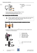
• Make sure that the LK2 connection has been removed.
• In-line resistor between positions 2 & 6 – R2.
• End-of-line resistor between positions 3 & 4 – R1.
7.3.6 Standard devices with LED status light
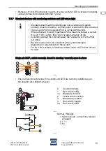
Single-pin MCP, switch normally open in standby / normally closed in alarm
• Ensure that connector wires from switch and LED are correctly installed as per
the diagram (see following figure).
17545E00
Active / Alarm
1 Switch open – In-line resistor
engaged
2 L / +
3 N / -
There is an 820 ohm resistor which is in-line with the LED. When activated,
the LED together with the resistor will draw a current. On a 24 V DC,
system this current is approximately 30 mA.
17567E00
17568E00
C
1
1a
2
3
4
Connector block
Red wire for LED
Black wire for LED
Yellow wire for switch
Blue wire for switch
Red wire for switch
17538E00
1
2
3
Cable connection (from right)
N / -
L / +
2
1
2
3
4
5
3
1
R1
6
7
R2
1a
2a
3a
4a
1
2
3
4
C
2
3
4
1
1a
C
LK1
TB1
LK3
1
Common
N/O
N/C
3
2
Lk2
Содержание MCP/PB
Страница 20: ......


