Mounting and installation
14
250306 / MCP60300050
2015-10-23·BA00·III·en·00
Flameproof Manual Call Points
Series MCP/PB
EN
EN
EN
EN
EN
EN
EN
EN
EN
EN
EN
EN
EN
EN
EN
EN
EN
EN
EN
EN
EN
EN
EN
EN
EN
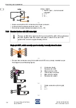
• Remove LK1 for LED activation in alarm or remove LK2 for LED activation in standby.
• Jumper/connection between terminal 1 and 2.
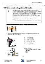
Two-pin MCP, switch normally closed in standby / open in alarm (independent circuits)
• Ensure that connector wires from switch and LED are correctly installed as per
the diagram (see following figure).
17570E00
C
1
1a
2
2a
3
3a
4
4a
Connector block
Red wire for LED
Black wire for LED
Yellow wire for switch
Yellow wire for second switch
Blue wire for switch
Blue wire for second switch
Red wire for switch
Red wire for second switch
17540E00
1
2
3
4
5
Cable connection (from right)
N / -
N / -
L / +
L / +
17567E00
17570E00
C
1
1a
2
2a
3
3a
4
4a
Connector block
Red wire for LED
Black wire for LED
Yellow wire for switch
Yellow wire for second switch
Blue wire for switch
Blue wire for second switch
Red wire for switch
Red wire for second switch
17541E00
1
2
3
4
5
Cable connection (from right)
N / -
N / -
L / +
L / +
2a
3a
4a
1
1a
C
2
3
4
LK1
TB1
LK3
1
Common
N/O
N/C
2
3
4
5
Lk2
1a
2a
3a
4a
1
2
3
4
C
2a
3a
4a
1
1a
C
2
3
4
LK1
TB1
LK3
1
Common
N/O
N/C
2
3
4
5
Lk2
Содержание MCP/PB
Страница 20: ......


