253215 / 941960310090
2017-04-21·BA00·III·en·01
Mounting and Installation
25
EN
EN
EN
EN
EN
EN
EN
EN
EN
EN
EN
EN
EN
EN
EN
EN
EN
EN
EN
EN
EN
EN
EN
EN
EN
Bus-Carrier for linking device
Series 9419/0..-LD1-..E1
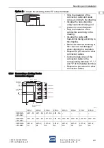
Option 2: Connect the shielding to the "S" screw terminals
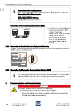
8.3.4 Connecting a Linking Device
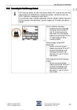
Connection diagram
18085E00
18084E00
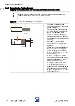
• Strip the insulation of the
connection cable and cable
cores according to the drawing.
• Insulate the bare shielding
using heat-shrink tubing and
press on core end sleeves.
• Strip the insulation of the
conductors according to the
drawing.
• Insulate the cable with
heat-shrink tubing according to
the drawing.
• Make sure that the shielding or
the cores are not damaged
when stripping the insulation.
• Repeat the procedure for other
connection cables.
• Connect single cores of the
connection cable to the
corresponding terminals "+", "–"
and "S" of the fieldbus terminal.
• Repeat the procedure for other
connection cables.
FPS 1
FPS 2
FPS 3
FPS 4
FPS 5
FPS 6
FPS 7
FPS 8
9419/04F-
LD1-01E1
LD1 - S1 LD1 - S2 LD1 - S3 LD1 - S4 –
–
–
–
9419/08F-
LD1-01E1
LD1 - S1 LD1 - S2 LD1 - S3 LD1 - S4 LD2 - S5 LD2 - S6 LD2 - S7 LD2 - S8
9419/04R-
LD1-02E1
LD1+2,
S1
LD1+2,
S1
LD1+2,
S2
LD1+2,
S2
LD1+2,
S3
LD1+2,
S3
LD1+2,
S4
LD1+2,
S4
7 [0,28]
40 [1,57]
6
5
4
3
2
1
RX
TX
GND
Link (RDL)
Redundancy
Power Supply
24V DC
L+
GND
GND
Rail Power Supply
24V DC
ETH1
ETH2
7
8
9
+
-
S
10
11
12
+
-
S
13
14
15
+
-
S
16
17
18
+
-
S
Fieldbus CH1
Fieldbus CH2
Fieldbus CH3
Fieldbus CH4
Fieldbus
CH1
CH2
CH3
CH4


