253215 / 941960310090
2017-04-21·BA00·III·en·01
Mounting and Installation
23
EN
EN
EN
EN
EN
EN
EN
EN
EN
EN
EN
EN
EN
EN
EN
EN
EN
EN
EN
EN
EN
EN
EN
EN
EN
Bus-Carrier for linking device
Series 9419/0..-LD1-..E1
8.3.2 Connecting the Fault Message Contact
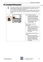
In the delivery status, the error message contacts "PF" (power fail) and "Dia"
(diagnostics) are connected by means of a jumper, resulting in only one
"error" collective message per bus-Carrier.
To use the two relay contacts separately, the wire jumper must be removed.
For the position of the terminals, see the chapter on "Function and device
design".
18038E00
"Error" collective message
• Connect the error message
contact to the terminals "5"
and "8" of the bus-Carrier.
Important: The wire jumper
between the terminals "6" and
"7" must remain in place
(delivery status).
Fault message contact "PF"
(power fail)
• Remove the wire jumper
between terminals "6" and "7".
• Connect the floating error
message contacts to the
terminals "5" and "6" of the
bus-Carrier.
"Dia" (diagnostics) fault message
contact
• Remove the wire jumper
between terminals "6" and "7".
• Connect the floating error
message contacts to the
terminals "7" and "8" of the
bus-Carrier.
1
2
3
4
8
7
6
5
pri 24V DC red
1+ 2- 3+ 4-
PF Dia
8
7
6
5

