Mounting and Installation
22
253215 / 941960310090
2017-04-21·BA00·III·en·01
Bus-Carrier for linking device
Series 9419/0..-LD1-..E1
EN
EN
EN
EN
EN
EN
EN
EN
EN
EN
EN
EN
EN
EN
EN
EN
EN
EN
EN
EN
EN
EN
EN
EN
EN
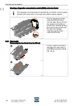
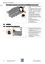
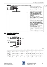
Dismounting the diagnostics communication module (DCM) from the bus-Carrier
8.3
Installation
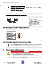
8.3.1 Connection of the Auxiliary Power
18033E00
• Pull the ribbon cable off of the
DCM:
To disengage the ribbon cable
connector, press the unlocking
actuators on the side together
using two fingers and pull the
cable upwards.
• Using a suitable screwdriver,
disengage the base bolts (1).
• Swivel the device towards the
bus-Carrier slightly (2) and then
remove it.
• Optionally, if desired:
Pull the ribbon cable off the
the bus-Carrier
(as described above).
18038E00
• Connect the auxiliary power to
terminals "pri 1+, 2-" (optionally
redundant "red 3+, 4-").
(Torque 0.5 to 0.6 Nm, auxiliary
power rated voltage 24 V DC).
• The connection line of the
auxiliary power must be
protected from tensile strain
and abrasion.
1
2
1
2
3
4
8
7
6
5
pri 24V DC red
1+ 2- 3+ 4-
PF Dia
8
7
6
5


