


Motor control operations
UM0432
40/53
The maximum current allowed by the GUI has been set to 8 A (see
Section 7.4.8
).
7.5.7 Stopping
the
motor (LED action)
Push the Start/Stop button to stop the motor. The LEDs toggle from green to red to indicate
an "idle" state.
7.5.8 Configuring
the
system for BEMF amplification
It is possible to configure the system to enable a BEMF amplification network. This
configuration can be useful in any circumstance where the BEMF signal is very low, such as
low speed for instance. This network can also compensate the free-wheeling diode voltage
drop, which is not negligible in the case of a low bus voltage value. See AN1103 "Improved
B-EMF detection for low-speed and low-voltage applications". Use the settings in
Table 16
to enable this feature.
7.5.9 Detecting
the
BEMF during the PWM on time
The direct back-EMF sensing scheme used by default by the STEVAL-IHM015V1
demonstration board, synchronously samples the motor back-EMF during PWM "off" time
without needing to sense or reconstruct the motor’s neutral point in a sensorless BLDC
motor drive system. Since this direct back-EMF sensing scheme requires a minimum PWM
"off" time to sample the back-EMF signal, the duty cycle cannot reach 100%. Furthermore,
in some applications, that is, HVAC using high-inductance motors, the zero crossing
detection is unsymmetrical at high speeds. It has been noted that the long settling time of a
parasitic resonant between the motor inductance and the parasitic capacitance of power
devices causes false zero crossing detections of the back-EMF. In such cases, the back-
EMF detection during PWM "on" time can be used to solve the problem.
More information on this issue can be found in the application notes AN2030, AN1946 and
AN1103. The STEVAL-IHM015V1 demonstration board can be configured to detect the
BEMF during the PWM "on" time.
Sampling of the BEMF can be performed using three different references.
●
Internal reference (default configuration)
●
V
Bus/2
external reference
●
Reconstructed neutral point external reference.
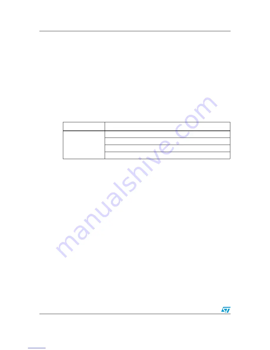
Table 16.
BLDC SL with BEMF amplification jumper settings
Driving mode
Jumper setting
BLDC_3PH_SL
J11 between 2-3, J12 between 2-3, J13 between 1-2
J15 between 2-3, J16 between 2-3, J17 between 1-2
J18 between 2-3, J19 between 2-3, J20 between 1-2
J3 Closed, J4 variable (2-3)
electronic components distributor