1B3-36 OM600 ENGINE MECHANICAL
Setting (with cylinder head installed)
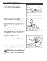
1. Remove the prechamber of No. 1 cylinder.
2. Position the piston of No.1 cylinder at BTDC 10.
3. Install the measuring device into the prechamber bore and
position the dial gauge with a preload of 5mm.
Dial Gauge 001 589 53 21 00
Depth Gauge 601 589 07 21 00
4. Slowly rotate the crankshaft in the direction of engine rotation
until the large pointer on the dial gauge stops (TDC position).
Notice
The position of TDC is when the large pointer on the dial
gauge is stopped before moving back.
5. remove the reinstall the measuring device and position the
dial gauge scale at ‘0’.
6. Slowly rotate the crankshaft in the direction of engine rotation
until the dial gauge has moved back (counterclockwise) by
3.65mm.
7. Insert fixing device into the sensor bracket.
Notice
The pin on the vibration damper must engage into the slot
of the fixing device.
Fixing Device 667 589 01 21 00
8. If the pin does not engage, adjust the setting of the sensor
bracket by removing and tightening of the sensor bracket
bolts.
Tightening Torque
10 Nm
Notice
The timing mark on the damper must be positioned at ATDC
20.
Содержание OM600
Страница 12: ...1B3 12 OM600 ENGINE MECHANICAL MAINTENANCE AND REPAIR ON VEHICLE SERVICE ENGINE ASSEMBLY ...
Страница 26: ...1B3 26 OM600 ENGINE MECHANICAL POLY V BELT ALIGNMENT INSPECTION Without Air Conditioner With Air Conditioner ...
Страница 51: ...OM600 ENGINE MECHANICAL 1B3 51 49 Remove the cylinder head 2 and gasket 3 OM661LA ...
Страница 145: ...OM600 ENGINE MECHANICAL 1B3 145 CHAIN TENSIONER 1 Chain Tensioner 80Nm 2 Seal Replace ...
Страница 171: ...1B3 172 OM600ENGINE MECHANICAL Oil Circulation ...
Страница 172: ...OM600 ENGINE MECHANICAL 1B3 173 Oil Filter a From Oil Pump b To Main Oil Gallery c To Oil Pan ...


