1B3-154 OM600 ENGINE MECHANICAL
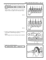
4. Position the no. 1 cylinder at the TDC of OT.
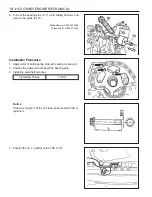
6. Pull out the bearing pins (9, 11) with sliding hammer and
remove the guide rail 10.
Sliding Hammer 116 589 20 33 00
Threaded Pin 116 589 02 34 00
Installation Procedure
1. Apply collar of both bearing pins with sealing compound.
2. Position the guide rail and insert the bearing pins.
3. Install the camshaft sprocket.
Tightening Torque
10 Nm
Notice
If the max. length ‘L’ of the 12-sided bolt exceeds 53.6mm,
replace it.
Содержание OM600
Страница 12: ...1B3 12 OM600 ENGINE MECHANICAL MAINTENANCE AND REPAIR ON VEHICLE SERVICE ENGINE ASSEMBLY ...
Страница 26: ...1B3 26 OM600 ENGINE MECHANICAL POLY V BELT ALIGNMENT INSPECTION Without Air Conditioner With Air Conditioner ...
Страница 51: ...OM600 ENGINE MECHANICAL 1B3 51 49 Remove the cylinder head 2 and gasket 3 OM661LA ...
Страница 145: ...OM600 ENGINE MECHANICAL 1B3 145 CHAIN TENSIONER 1 Chain Tensioner 80Nm 2 Seal Replace ...
Страница 171: ...1B3 172 OM600ENGINE MECHANICAL Oil Circulation ...
Страница 172: ...OM600 ENGINE MECHANICAL 1B3 173 Oil Filter a From Oil Pump b To Main Oil Gallery c To Oil Pan ...

