background image

4

Installation

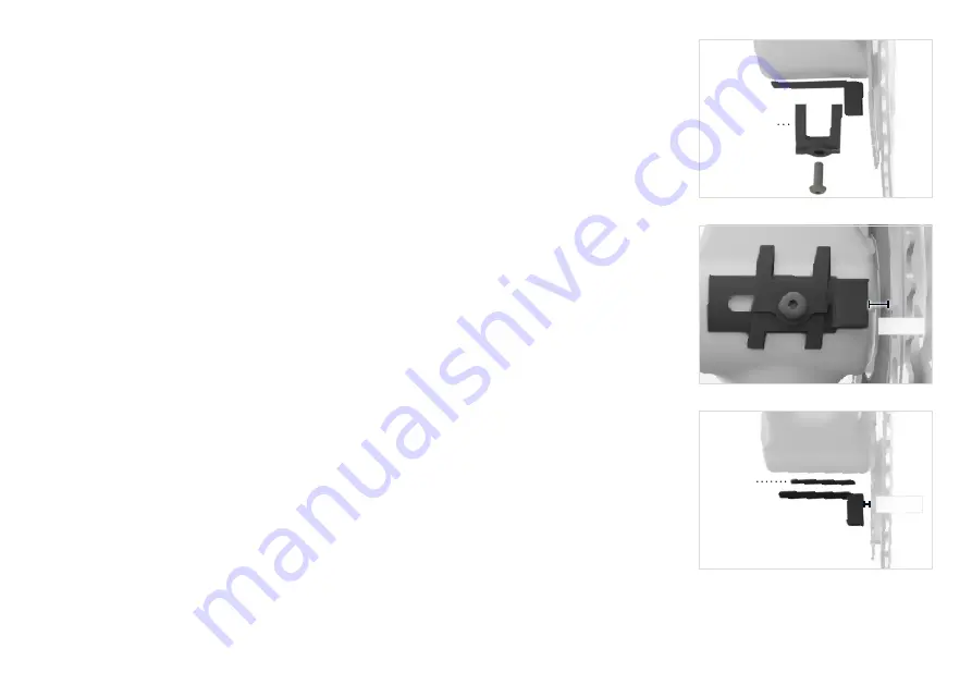
Option 1: For frames with a cable guide: 

1.  Remove the cable guide bolt and install the magnet under the cable guide. 

2.  Position the magnet 4-6 mm from the backside of the PowerMeter. 

3. 

Install the bolt and tighten it to the torque specified by the frame manufacturer. 

To assist with cable guide removal, shift the chain into the largest cog in the rear and the 
largest chainring in the front. Next, without turning the cranks, shift both derailleurs to the 
smallest cog. This will remove tension from both cables.

Note: The derailleurs may require some adjustment after cadence magnet installation. 

Option 2: For frames without a cable guide: 

1.  Clean both the magnet and the mounting surface of the frame with the alcohol swab 

provided.

2.  Position the magnet 4-6 mm from the backside of the PowerMeter. It is recommended to 

temporarily fix the magnet in place and confirm correct position before installing with the 

double sided tape.

3.  Use the double sided tape to install the cadence magnet to the frame. Remove the 

protective film on each side of the tape. Avoid touching the adhesive surfaces.

To achieve optimal magnet position, the cadence magnet and double sided tape can be 

cut with scissors to fit your desired location.


 If your frame geometry does not allow for these magnet positions, visi

http://store.      

     srm.de/ 

for integrated chain catcher magnets and additional mounting options.

cable guide

tape

4

-6 

mm

4

-6 

mm

Содержание Cadence Magnet

Страница 1: ...System User Manual www SRM de Revision 07132016 2016 SRM GMBH...

Страница 2: ...e PC8 or head unit manual for setting the zero offset You should now receive correct power and cadence data To receive data from accessories such as speed and heart rate Install ANT speed sensor heart...

Страница 3: ...ter Training System Components Components sold as a complete system and sold separately Additional accessories can be found at http store srm de accessories html Heart Rate Strap PowerControl Handleba...

Страница 4: ...nce Magnet Installation Options 1 The recommended position for the cadence magnet is on the underside of the bottom bracket 2 Make sure the magnet is positioned between 21 51 mm from the center point...

Страница 5: ...on 2 For frames without a cable guide 1 Clean both the magnet and the mounting surface of the frame with the alcohol swab provided 2 Position the magnet 4 6 mm from the backside of the PowerMeter It i...

Страница 6: ...tery cover faces away from the spokes 2 Install the speed sensor magnet onto the spoke of the front wheel 3 Align the magnet with the timing mark on the sensor Make sure there is 1 4 mm between the se...

Страница 7: ...screen For SRM PowerMeters with non rechargeable solid state batteries or rechargeable batteries when the battery has been depleted or no longer holds a charge the SRM PowerMeter will need to be retur...

Страница 8: ...perly installed 3 any product that has been subject to abuse misuse neglect alteration abnormal use or accident 4 any defects or damage directly or indirectly caused by the unauthorized replacement pa...

Страница 9: ...bished PowerMeters and PowerControls are covered with a one year limited warranty to be free from defects in materials or workmanship Within this period SRM will at its option repair or replace any co...

Страница 10: ...ontact SRM USA for specific prices Crash Replacement Details The Customer must Return the damaged part or product to SRM USA at the customer s expense Provide an Original Sales Receipt or Proof Of Pur...

Страница 11: ...cations if not installed and used in accordance with the instructions However there is no guarantee that interference will not occur in a particular installation If this equipment does cause harmful i...

Страница 12: ...SRM USA 720West Monument Street Colorado Springs CO 80904 USA Phone 1 719 266 4127 Fax 1 719 266 4284 Web www SRM de...

Отзывы: