SPX Waukesha Cherry-Burrell CM Скачать руководство пользователя страница 14

95-03028

08/2010

14

Tools required for seal and/or bearing replacement:

• Assorted hand tools including soft hammer.

• Bearing puller or press.

• Hook tool for seal removal.

• Spanner wrench for bearing retainer nut removal

• Wrench GD0019000 for rotor nut..

• Anti-seize and seal lubricating grease.

• 2 quarts DTE BB Mobil oil or equivalent.

service Preparation

1. 

shut OFF and lock out all power.

2.

 Remove all product and flushing from mill.

3. 

Disconnect all piping to mill.

4. Remove pump anchor screws and slide gearcase 
off motor coupling.
5. Place mill on sturdy work surface.
6.

 Disassemble wet end of mill completely. (See 

Page 11 for Disassembly)
7. Drain oil from gear case. 
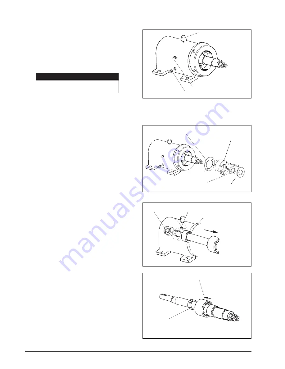
(Figure 18)

Front seal Replacement

 (Figure 19)

1. Remove slinger. 

(Pull off)

2. Remove bearing retainer assembly (front seal 
inside) 

(Held in place with four (4) capscrews).


4. Note seal lip position and knock out old seal, place 
lubrication around new seal and press into bearing 
retainer. Replace gasket, if necessary. Lubricate seal 
lip and install bearing retainer and slinger.

Rear seal Replacement 

(Figure 20)

1. Pull rear oil seal off drive shaft with hooked tool. 
2. Place tape over shaft keyway and install new seal. 

(Lubricate seal lip before sliding onto shaft).

bearing Replacement

1. Remove rear seal. Remove rear bearing retaining 
ring. Press drive shaft out through front of gear case 
(through rear bearing). (Figure 20)
2. Remove bearing locknut from shaft (counter-
clockwise) and press front bearing off. (Fig. 19)
3. Press the rear bearing out of the front of gear 
case. (Fig. 20) 
4. Clean and lubricate all parts thoroughly before 
reassembling. 

Do not unwrap new bearings until 

ready to install.


5. Lubricate inner races and press new bearings onto 
shaft. Tighten locknut on front bearing to 40 ft-lbs. 
(Fig. 21)
6. Lubricate outer races and press shaft assembly 
into case. Replace retaining ring and rear seal. (Fig. 
17) 
7. Replace mill assemblies.  Torque rotor nut to 75 ft- 

lbs. Refill crankcase with 2 quarts Mobil DTE BB oil.


Figure 18


Figure 19


Figure 20


Figure 21

beaRInG ReTaIneR 
asseMblY

slInGeR

    OIl leVel
OIl DRaIn

 
GaskeT


FROnT beaRInG

lOcknuT

FROnT seal

  ReaR seal       ReTaInInG RInG


    ReaR beaRInG

GeaR case seRVIce

MaInTenance

bReaTheR caP

To avoid cutting injury, wear gloves 

and handle parts carefully.

cauTIOn

Содержание Waukesha Cherry-Burrell CM

Страница 1: ...Instruction Manual Colloid Mill Read and understand this manual prior to operating or servicing this product ...

Страница 2: ...ge without notice and does not represent a commitment on the part of SPX Corporation No part of this manual may be reproduced or transmitted in any form or by any means electronic or mechani cal including photocopying and recording for any purpose without the express written permission of SPX Corporation Copyright 1997 2010 SPX Corporation All Rights Reserved Revision Date 08 2010 Publication 95 0...

Страница 3: ...AD EQUIPMENT 7 3 WIRING 8 4 ROTATION 8 5 SEAL FLUSH 8 6 LUBRICATION 8 7 METHOD OF FEEDING AND CAPACITY 8 COLLOID MILL troubleshooting 9 MAINTENANCE 10 CLEANING 10 A FLUSHING 10 B PARTIAL DISASSEMBLY 10 C COMPLETE DISASSEMBLY 10 D ASSEMBLY 12 ADJUSTMENT AND CALIBRATION 12 FLUSH WATER SEAL REPLACEMENT 13 GEAR CASE SERVICE 14 SANITARY SEAL REPLACEMENT 15 PARTS LIST 15 SANITARY SEAL 15 colloid mill GE...

Страница 4: ...of merchantability of fitness for a particular purpose The foregoing sets forth Seller s entire and exclusive liability and Buyer s exclusive and sole remedy for any claim of damages in connection with the sale of products In no event shall Seller be liable for any special consequential incidental or indirect damages including without limitation attorney s fees and expenses nor shall Seller be lia...

Страница 5: ...safe practices which COULD result in minor personal injury or product or property damage NOTE Important information pertaining directly to the subject Information to be aware of when completing the task To avoid electrocution ALL electrical should be done by a registered Electrician following Industry Safety Standards All power must be OFF and LOCKED OUT during installation WARNING MILL PARTS HAVE...

Страница 6: ...the maximum 150 psi feed pressure 4 31 110 8 63 219 10 00 254 6 00 152 12 00 305 1 50 38 TYP 8 56 217 13 75 349 MIN 14 88 378 MAX 9 38 238 MIN 10 51 267 MAX 17 44 443 26 81 681 AS SHOWN WITH STATOR ALL THE WAY IN 27 94 710 WITH STATOR ALL THE WAY OUT 3 00 76 Ø1 50 38 1 65 42 Ø 56 14 38 KEY 10 2 8 IMDA INLET 2 8 IMDA OUTLET 1 4 18 NPT PIPE NIPPLE SEAL FLUSH OUTLET 1 4 18 NPT PIPE NIPPLE SEAL FLUSH ...

Страница 7: ...e mill is shipped from the factory with the inlet port as shown in Position 1 Forconvenience theinletportcanberelocatedtoanyof theotherthreepositions seeDisassemblyProcedure If Position 4 is used the calibrations at the pointer will be upside down We suggest the use of a mirror 2 OVERHEAD EQUIPMENT Follow accepted engineering practice when connect ing inlet and outlet with overhead equipment pipin...

Страница 8: ...and moisture conditions If room temperature is normal 70 to 80 F and water does not contact the bearing case change oil every 240 operating hours When temperature varies from hot to cold or mill is flushed out with water condensation will occur in the bearing case necessitating more frequent oil changes Normal operating temperature of the bear ing case is 170 F to 190 F 3 WIRING 3 Phase 60 Cycle 2...

Страница 9: ... gland Water pressure too high Adjust to 1 2 one quart per minute Seals misaligned on pins Re align seals to proper fit Noisy operation Excessive power draw Loose rotor nut causing rotor to stator contact Tighten nut to 75 ft lbs Check mill rotation counterclockwise facing outlet port Inconsistant milling results Loose adjusting ring Set gap and tighten knurled screw in hole Tighten bolt and nut o...

Страница 10: ...earing of the faces between the adjusting ring and stator it is recommended that these surfaces be lubricated occasionally with an approved silicone type lubricant T HANDLE KNURLED LOCK SCREW Figure 7 o ring adjusting ring Figure 8 MAINTENANCE C COMPLETE DISASSEMBLY 1 Follow 3 steps outlined in B 2 Remove cover capscrews and pull off cover then remove the o ring 3 Pull stator off studs and remove ...

Страница 11: ... hex nuts which secure body to bearing case and slide body off 9 Remove four capscrews from gland on back side of body and disassemble gland There are six loose springs in the gland The gland lip seal can be pressed out if replacement is required 10 Remove o ring from inside body Use o ring tool if necessary NOTE Clean and inspect all parts thoroughly DO NOT reuse seal or seal seat if scratched ch...

Страница 12: ...ingcounterclockwise whenfacing theoutletport forincreasedclearanceandclockwiseto decrease the clearance The adjusting ring is engraved with numerals indicating the clearance in increments of 010 inches The indicator pointer indicates the desired clearance For setting in between the increments of 010 the drill point spacing is equal to 001 clearance Drill point spacing coincides with locking hole s...

Страница 13: ...four nuts Figure 15 remove body nuts 4 remove body Replace lip seal 3 Slide body 1 forward off shaft Figure 16 4 Pull seal out with hook tool Insert new water lip seal with lip facing in See Item 18 Figure 22 5 Re assemble in reverse order FLUSH WATER SEAL REPLACEMENT MAINTENANCE Figure 15 Figure 16 Figure 17 ...

Страница 14: ...ger Rear Seal Replacement Figure 20 1 Pull rear oil seal off drive shaft with hooked tool 2 Place tape over shaft keyway and install new seal Lubricate seal lip before sliding onto shaft Bearing Replacement 1 Remove rear seal Remove rear bearing retaining ring Press drive shaft out through front of gear case through rear bearing Figure 20 2 Remove bearing locknut from shaft counter clockwise and p...

Страница 15: ...n process ing food products 8 Lubricate remaining o ring 24 with compatible lubricant and install on small O D of seat 21 9 Install seat 21 with pins and o ring into rear of rotor aligning pins with holes in rotor 10 Install rotor onto shaft being careful to avoid damage to the seat 21 or seal 20 Tighten rotor nut to 75 ft lbs 11 Complete mill assembly Reverse steps 2 and 3 on page 13 SANITARY SEA...

Страница 16: ...95 03028 08 2010 16 colloid mill GEAR case Figure 23 PARTS LIST ...

Страница 17: ... 7 Front Bearing Retainer Gasket 1 0MS042B00 8 Front Bearing Retainer 1 0MS080000 9 Pump End Shaft Seal 1 0MS030100 10 Capscrew 4 30 274 11 Drive End Shaft Seal 1 0MS030000 12 Slinger 1 0MS045000 13 Breather 1 115800 14 Level Indicator 1 115799 15 Drain Plug 1 115798 48 Nameplate Sanitary 1 001061002 49 RHDS 6 30 355 50 Caution Label Yellow 1 33 62 51 Key 1 000037003 52 Rotor Nut Wrench 1 109896 P...

Страница 18: ...e 24 colloid mill Fluid head NOTE Torque rotor nuts to 75 ft lbs Used to set adjusting ring at minimum setting of 0 010 Used to hold adjusting ring setting NOTE Body rotor clearance starts at 0 101 and ends at 0 220 in increments of 0 010 ...

Страница 19: ...O ring Rotor Nut FKM 1 V70222 O ring Rotor Nut Silicone 1 S75222 33 Rotor 1 0MS010000 34 Rotor Retaining Nut 1 0MS052000 35 Stator 1 0MS004000 36 O ring Stator FKM 1 V70263 O ring Stator Silicone 1 S75263 37 Stud Handle Shaft 4 0MS011100 38 Handle Shaft 4 0MS099000 39 Handle Pin 4 0MS100000 40 Cover 2 Bevel Seat 1 0MS002000 Cover 2 TCF 1 35887 41 O ring Cover FKM 1 V70253 O ring Cover Silicone 1 S...

Страница 20: ...95 03028 08 2010 20 NOTES ...

Страница 21: ......

Страница 22: ...local representatives please visit www gowcb com SPX Corporation reserves the right to incorporate our latest design and material changes without notice or obligation Design features materials of construction and dimensional data as described in this bulletin are provided for your information only and should not be relied upon unless confirmed in writing Issued 08 2010 95 03028 Copyright 1997 2010...

Отзывы: