


51
0450
0030
0801
0250
0020
0171
0800
0802
0087
0085
0080
0130
0082 0182
0088 0086
0101
0083
0090
0804
0080
0802
0101
0088
0082
0085
0083
Double seal
0095
0182
0087
0090
0130
0804
0086
0082
0090
0802 0080
0130
0083
0101 0088
0085 0087
0086
0540
0804
0936
0936
0540
0540
0936
TL4
High ,low and medium pressure
TL2/TL3
High pressure
TL2/TL3
Low and medium pressure
TL2/0074, TL3/0234
TL2/0234, TL2/0301,
TL3/0677, TL3/0953
TL4/0535, TL4/2316, TL4/3497
A.0500.251 – IM-TL/13.00 EN (08/2009)
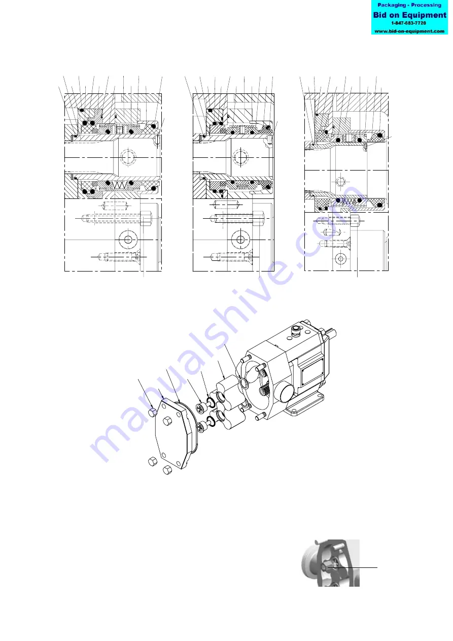
4.7.6 Rotor and pump cover assembly
1.
Place the shims (0171) in chamber in the rotors.
2.
Place the rotors (0020) on the shaft. The rotor for the drive shaft is marked with
a
∆
.
3.
Block the rotors against each other by putting a block of soft material between
the rotors.
4.
Tighten the retainer (0250) clockwise with
the correct torque (see section 4.5 Tightening
torques for nuts and screws) by using the
retainer tool.
retainer tool