


16
a
b
c
d
e
A.0500.251 – IM-TL/13.00 EN (08/2009)
The pump is not to be exposed to rapid temperature changes to avoid damage through
sudden expansion/contraction of the pump components.
Pumps for handling abrasive liquids (causing wear) should be selected with care. Please
contact your local distributor for advice.
Important!
If it is proposed to modify the system/duty or to use the pump for transporting liquids
with other characteristics than for which the pump was originally selected always consult
your distributor.
2.2 Operating parameters
The maximum pressure and speed operating data are given in the table below. In
practice these performance data can be limited by the nature of the pumped media
and/or the design of the system in which the pump is installed.
2.0 Function, design, installation
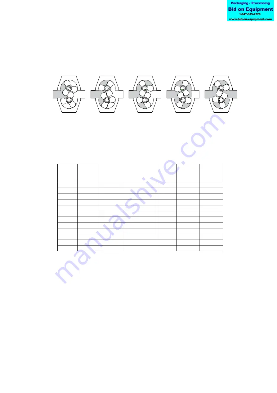
2.1 Operating principle
Liquid is drawn into the pump as the rotors disengage, forming cavities. The liquid is
transported in the cavity of the rotors around the periferi of the rotor case. Liquid is
pressured out from the pump as the rotors engage, closing the cavities.
Max pump speed = n
max
Swept volume
= Vi
Theoretical capacity at
max speed and
∆
p = 0 bar = Qth
max
Max differential pressure =
∆
p
max
Max operating pressure
= p
max
Max torque on shaft end = T
max
Pumptype
Max
pump
speed [rpm]
Swept volume
[dm
3
]
Theoretical capacity
at max speed and
∆
p = 0 bar
[m
3
/h]
Max
differential
pressure
[bar]
Max
operating
pressure
[bar]
Max torque
on shaft end
[Nm]
TL1/0039
1450
0.039
3.4
22
25
53
TL1/0100
950
0.100
5.7
12
15
53
TL1/0139
950
0.139
7.9
7
10
53
TL2/0074
1450
0.074
6.5
22
25
108
TL2/0234
950
0.234
13.3
12
15
108
TL2/0301
950
0.301
17.1
7
10
108
TL3/0234
1200
0.234
16.8
22
25
400
TL3/0677
720
0.677
29.2
12
15
400
TL3/0953
720
0.953
41.2
7
10
400
TL4/0535
950
0.535
30.5
22
25
1200
TL4/2316
600
2.316
83.4
12
15
1200
TL4/3497
600
3.497
125.9
7
10
1200