5
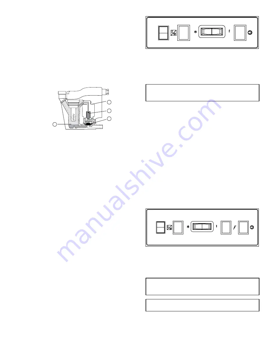
B. Condensate enters the reservoir
(1)
through the inlet
port. When the condensate level in the reservoir covers
the capacitance sensor, an electronic signal is sent to the
solid state countdown processor. The processor delays
the opening of the solenoid valve for a given period
of time. Once the time has elapsed, the solid state
processor transmits information to energize the coil in
the solenoid valve
(2)
. The magnetic force of the coil
causes the solenoid core
(3)
to move, closing the pilot air
supply line and opening the pilot air exhaust line. After
the pilot air above the diaphragm
(4)
is vented, pressure
in the reservoir opens the discharge port and forces
the condensate through the discharge port and outlet
piping.
2.0 DRYER OPERATION
Basic Theory of Operation: This energy savings dryer
operates using a glycol/air heat exchanger to absorb
heat from the air stream. A refrigeration compressor is
used to cool the glycol mixture and when the dryer load
is reduced, the excess cooling from the compressor is
used to lower the temperature of the glycol. When the
glycol reaches a minimum temperature, the compressor is
turned off to save energy. The dryer continues to operate
by using the glycol mixture to cool the air stream until the
glycol reaches a maximum temperature set point at which
time the compressor again turns on to cool the glycol
mixture.
2.1 Minimum/Maximum operating conditions
A. Maximum inlet air pressure: refer to dryer serial number
tag
B. Minimum inlet air pressure: 30 psig (2.1 kgf/cm
2
)
C. Maximum inlet air temperature: 130°F (54°C)
D. Maximum ambient temperature:
Air-cooled models: 110°F (43°C)
Water-cooled models: 130°F (54°C)
E. Minimum ambient temperature: 40°F (4°C)
2.2 Start-up
A. Models 90-140: Standard Controller
Energize compressor by positioning the on/off switch
in the on (I) position. Power on light will illuminate.
Compressor on light will illuminate. Compressor will
run until glycol mixture is cooled. The refrigeration unit
will then turn off, and the compressor on light will be
extinguished.
SLOWLY pressurize the dryer with compressed air. Fully
open the inlet and outlet valves. Dryer will operate
automatically and the compressor will cycle in response
to the air load.
On/Off
Dryer On
Dewpoint
Compressor On
Switch
Light
Indicator
Light
B. Models 190-675: Standard Controller
Energize dryer by applying power to the unit. The green
dryer energized light will illuminate.
NOTICE: Energize dryer for 24 hours prior to starting
refrigeration compressor! Failure to follow these notices
may result in a non-warrantable compressor failure.
Energize compressor by positioning the on/off switch
in the on (I) position. Power on light will illuminate.
Compressor on light will illuminate. Compressor will
run until glycol mixture is cooled. The refrigeration unit
will then turn off, and the compressor on light will be
extinguished.
NOTE: Check for correct phasing of unit.
On air-cooled models: check fan rotation (air must be
pulled through the condenser). Fans may not start
immediately or may cycle on and off. If rotation is in the
wrong direction follow the procedure below.
On water-cooled models: After starting dryer if an
unusual noise is heard and the discharge line does not
get hot, stop the dryer, reverse two power leads, restart,
and verify discharge line gets hot.
SLOWLY pressurize the dryer with compressed air. Fully
open the inlet and outlet valves. Dryer will operate
automatically and the compressor will cycle in response
to the air load.
On/Off
Power-On
Dewpoint
Dryer
Compressor
Switch
Light
Indicator
Energized
On
Light
Light
C. Models 190-675: Advanced Controller (EMM)
Energize dryer. Green power on light will illuminate.
NOTICE: Energize dryer for 24 hours prior to starting
refrigeration compressor! Failure to follow these notices
may result in a non-warrantable compressor failure.
NOTICE: Do not use disconnect switch to remove power from
dryer for extended periods except for dryer repair.
1
2
3
4
Содержание HANKISON HES Series
Страница 16: ...16 WIRING DIAGRAM Standard Controller Model 675 Sheet 1 of 2...
Страница 17: ...17 WIRING DIAGRAM Standard Controller Model 675 Sheet 2 of 2 RTD...
Страница 18: ...18 WIRING DIAGRAM Advanced controller Models 190 540 460 VAC Sheet 1 of 2...
Страница 19: ...19 WIRING DIAGRAM Advanced controller Models 190 540 460 VAC Sheet 2 of 2...
Страница 20: ...20 WIRING DIAGRAM Advanced controller Model 675 460 VAC Sheet 1 of 2...
Страница 21: ...21 WIRING DIAGRAM Advanced controller Model 675 460 VAC Sheet 2 of 2...
Страница 22: ...22 WIRING DIAGRAM Models 190 675 575 460 3 60 Transformer Pack...
Страница 27: ...27 NOTES...


