1-6.
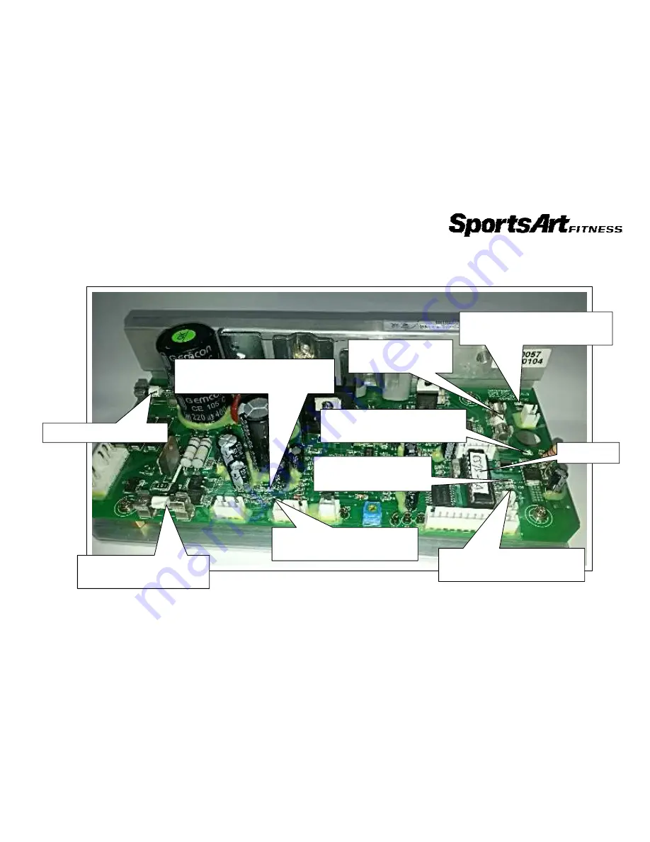
Drive Board Indicator LEDs – C575R/U
1-6-2
F1 Alternator fuse 3A
LED 5 COMM
Communication indicator
F3 battery charged fuse
2A
F2 Battery fuse
2A
LED 3 VBB
Lit = Vbb power indicator
LED 4 HTR (C575R)
Lit, HTR indicator
LED 1 CLK
Speed sensor indicator
LED 6 VCC power
Lit, Vcc power indicator
LED 2 Battery charge
Lit, Battery is being charged.
Program
Содержание C575U
Страница 1: ...C575U Repair Manual Electronics...
Страница 2: ...1 1 Product Picture C575U 1 1 1...
Страница 3: ...1 2 Display picture C575U 1 2 1...
Страница 4: ...1 3 Component Placement C575U Display 1 3 1 Dispaly Program board Polar board USB board...
Страница 6: ...1 3 Component placement C575U lower body C575U 1 3 2 Battery 1 Electro magnet Model board Alternator...
Страница 8: ...1 5 C575U...
Страница 12: ...1 6 Display Board Indicator LEDs C575R U 1 6 1 Power...
Страница 24: ...C575 1 2 C575 E875 3 11 1 JP1 JP2 JP3 JP4 JP16 C575R U JP2 JP1 JP3 JP16...


