7
www.spokey.pl
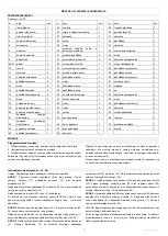
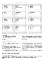
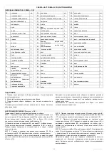
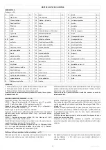
LIST OF PARTS - DIAGRAM
– P. 36
No.
Description
Qty
No. Description
Qty
No. Description
Qty
1
main frame
1
25
knob
1
49
ring bearing
2
2
front stabilizer
1
26
sleeve in the seat post
1
50
bearing seat
2
3
rear stabilizer
1
27
end cap
2
51
nut
1
4
handlebar post
1
28
crank
1
52
washer
1
5
handlebar
1
29
screw
1
53
nut
1
6
seat
1
30
pulse sensor wire (from the
handlebar post)
1
54
magnet fastening
1
7
seat post
1
31
foam
2
55
bolt
1
8
extension
1
32
pulse sensor wire
2
56
hexagon nut
2
9L/R
pedal
2
33
counter bracket
1
57
hexagon screw
2
10
counter
1
34
resistance control wire
1
58
spring washer
2
11
pin
2
35
resistance control cover
1
59
flat washer
2
12
acorn nut
2
36
flat washer
1
60
spring washer
2
13
curved washer
2
37
screw
1
61
resistance spring
1
14
bolt
8
38
flat washer
3
62
magnet
7
15
flat washer
4
39
curved washer
4
63
axle
1
16
spring washer
2
40
flywheel axle
1
64
hexagon nut
2
17
bolt
2
41
flywheel
1
65
screw
2
18
handlebar cover
1
42
screw
2
66
U-shaped washer
2
19
resistance control wire
1
43
screw
5
67
nut
2
20
pulse sensor wire
1
44
cover
2
68
thin washer
2
21
rear stabilizer end cap
2
45
drive belt
1
69
bearing
2
22
front stabilizer end cap
2
46
drive pulley
1
70
plastic insert
1
23
nylon nut
3
47
big washer
1
71
sensor
1
24
foam
1
48
nut
1
PREPARATIONS
1. Before assembly make sure there is enough space.
2. Use the recommended tools.
3. Before assembly check if there are all the parts in the box.
It is recommended that product should be assembled by at least two people
to avoid injuries.
Most of the assembly equipment listed here has been packed separately,
but some elements come preassembled in certain assembly parts. If it is
required, dissassemble them and assemble again.
Read the instructions of all assembly steps and familiarize with all the
devices installed.
ASSEMBLY INSTRUCTIONS (
Drawings
– p.
38)
Note: Follow the assembly instructions below:
STEP 1 Fix the front stabilizer (2) to the main frame (1) with the screws
(11), curved washers (13) and acorn nuts (12).
Next use the flat washers (15) and bolts (14) to fix the rear stabilizer (3) to
the main frame.
Place the end caps on the front (22) and rear stabilizer (21).
Next, fix the pedals (9L/R) on the crank. Screw in the right pedal clockwise
and the left one
– counterclockwise.
STEP 2 Connect the resistance control wires (19, 34) and pulse sensor
wires (20, 30) coming from the post and the main frame.
Put the handlebar post (4) onto the proper element of the main frame (1),
screw both elements together using the curved washers (39) and bolts (14).
STEP 3 Pull the pulse sensor wires (32) through the handlebar post (4).
Screw the handlebar (5) into the post using the spring washers (16) and
bolts (17). Place the plastic cover (18) on the mounted handlebar.
STEP 4 Pull the wires coming from the counter through the counter base
(33). Connect the pulse sensor wires (32) and resistance control wires (20)
coming from the handlebar post with their equivalents coming from the
counter. Mount the counter (10) on the base (33).
STEP 5 Fix the seat (6) on the top of the seat post (7) with the washers
(38) and nylon nuts (23). Next insert the post together with the extension
(8) into the proper element of the main frame (1). Fix the post by turning
the knob (25).
NOTE: before you start the training, make sure that all the bolts and nuts
are securely tightened.
Remember to check if the blind of the front stabilizer is moveable, which
will make it easier to move the bicycle to another place.
The blinds of the back stabilizer are used to level the bicycle.
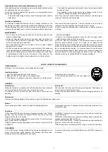
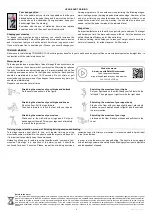
Levelling and Moving the device (pictures p. 41)
Before you start exercising, it is recommended to verify whether the bike is
positioned correctly. Please level the equipment by means of the stabilizer
knobs
To transport the device, raise it carefully on its front wheels (Figure
– p. 41)
and move to another place, holding it on both sides.
ASSEMBLY, SETUP AND MAINTENANCE
Содержание TIDAL
Страница 11: ...10 www spokey eu 22 4 74 x 50 x 113 100 2 a 100 H C RU...
Страница 15: ...14 www spokey eu 5 WEE...
Страница 36: ...35 www spokey eu...
Страница 38: ...37 www spokey eu SCHEMAT DIAGRAM SCH MA SCHEMA SH MA SCHEMA...
Страница 39: ...38 www spokey eu 1 KROK STEP INGSNIS SOLIS SCHRITT 2 KROK STEP INGSNIS SOLIS SCHRITT...
Страница 40: ...39 www spokey eu 3 KROK STEP INGSNIS SOLIS SCHRITT 4 KROK STEP INGSNIS SOLIS SCHRITT...
Страница 41: ...40 www spokey eu 5 KROK STEP INGSNIS SOLIS SCHRITT...


