26 Operations Manual
–
Wall Extruder (Frame Nailer Gen IV and Tables)
9.5
Guns in correct position
The upper nail gun has two positions but is fixed in relation to the lower nail gun. The upper nail gun
can be set to suit either 70mm or 90mm timber, up to a maximum offset of 20mm above the lower
nail gun. The offset of the upper nail gun is an automatic setting that is controlled by the operating
computer. The computer uses the preset specifications to detect the size of the timber being added,
and automatically adjusts the gun heights accordingly; however, be sure to check that gun offset has
been set correctly for the timber that is being added before firing.
Caution:
When processing 70mm wide timber the nail gun is set to the Down Position
.
9.6
Trolley and Carriage Clamps
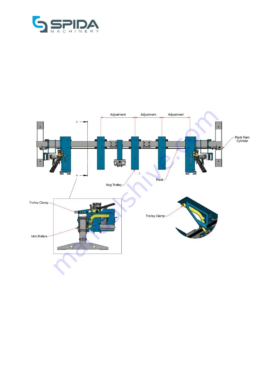
Figure 6, Nog centres adjustment
The position of the Nog Trolleys can be adjusted horizontally as in Figure 6 to achieve different nog
centres. By squeezing the Trolley Clamp at the top of the Nog Trolley, the Trolley Clamp is released
from the beam and the Unit Rollers are free to move; allowing the Nog Trolley to be adjusted as
required. By letting go of the Trolley Clamp, the Trolley Clamp is applied to the beam and the Nog
Trolley is horizontally locked. The Nog Trolleys must be locked in place before attempting to fire the
guns.
The position of the Floating Carriage assembly can be adjusted to suit different frame sizes. The
carriage must be set to the correct framing height required PLUS ~5mm; to allow for the addition of
timber components.
Apply the pneumatic brake switch (Figure 2, Item 9) once the required framing height has been set;
this activates the carriage clamp and stops the floating carriage assembly from moving freely along
the beam.
Содержание Wall Extruder
Страница 1: ...OPERATION MAINTENANCE MANUAL ...
Страница 68: ...67 Operations Manual Wall Extruder Frame Nailer Gen IV and Tables Figure 25 Electrical Drawings Part 2 ...
Страница 69: ...68 Operations Manual Wall Extruder Frame Nailer Gen IV and Tables Figure 26 Electrical Drawings Part 3 ...
Страница 70: ...69 Operations Manual Wall Extruder Frame Nailer Gen IV and Tables Figure 27 Electrical Drawings Part 4 ...
Страница 71: ...70 Operations Manual Wall Extruder Frame Nailer Gen IV and Tables Figure 28 Electrical Drawings Part 5 ...
Страница 72: ...71 Operations Manual Wall Extruder Frame Nailer Gen IV and Tables Figure 29 Electrical Drawings Part 6 ...


