Instruction manual for Water-cooled Air Compressor HV2/210 - 11 -
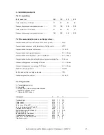
6. TECHNICAL DATA
T.1. Coolant flows
Shaft speed rpm.
580
-
725
-
875
-
975
Coolant flow l/min. 7-10 bars................................ :
17
-
21
-
26
-
28
Pressure drop across compressor (mm.w.c.)....... :
110
-
180
-
280
-
350
Coolant flow l/min. 15-35 bars.............................. :
21
-
26
-
32
-
35
Pressure drop across compressor (mm.w.c.)....... :
180
-
280
-
440
-
550
T.2. Recommended pressures and temperatures
Recommended minimum inlet temperature Cooling water .................... : 30
o
C
Recommended maximum outlet temperature Cooling water ................. : 60
o
C
Recommended temperature difference.................................................. : 15 - 20
o
C
Recommended cooling water pressure.................................................. : 0.5 - 3.0 bars
Recommended lube oil pressure, warm compressor ............................. : 2.0 - 0.8 bars
Recommended limit switch setting for lube oil pressure/safety stop ...... : 0.8 bars
Normal working pressure one stage 0-10 bars ...................................... : 1.5 - 3.5 bars
Normal working pressure one stage 10-35 bars .................................... : 4.0 - 6.0 bars
Maximum working pressure.................................................................... : 35 bars
Safety valve setting over stage pressure................................................ : 10%
Normal temperature outlet air................................................................. : 30 - 65
o
C
T.3. Torque table
A - Thread diameter (mm)
B - Key width
C -Torque (kpm), clean and lubricated threads
* - Marker for unbrako screw
** - Marker for BSP threads
Component
A
B
C
Cylinder head ....................................................... :
M20
30
20
Cooler cover ......................................................... :
M16
24
15
Cooler cover ......................................................... :
M12
19
8
Valve cover HP and LP ........................................ :
M16
24
15
Valve clamping screw HP and LP ........................ :
*M20
10
12
Cap lock nut HP and LP ....................................... :
M20
30
10
Big end bearing bolts HP and LP ......................... :
**1/4
22
9-10
Main bearing studs ............................................... :
M12
19
8
Bearing housing, crankcase ................................. :
M10
17
4
Cylinder block to crankcase ................................. :
M22
32
25
Hand hole – Air intake manifold ........................... :
M12
19
8
Crankcase covers................................................. :
M10
17
4
Содержание HV2/210
Страница 16: ...Fig 1 Instruction manual for Water cooled Air Compressor HV2 210 15...
Страница 17: ...Instruction manual for Water cooled Air Compressor HV2 210 16...
Страница 18: ...Instruction manual for Water cooled Air Compressor HV2 210 17...
Страница 19: ...Instruction manual for Water cooled Air Compressor HV2 210 18...


