Instruction manual for Water-cooled Air Compressor HV2/210 - 3 -
2.2. Safety equipment
The compressor is fitted with two safety valves, one after the first-stage compression and the other after second-
stage compression.
The safety valves, which are set at the factory in accordance with the working pressure specified by the
customer, ensure that the pressure does not exceed the limit for which the compressor and the compressed air
system are dimensioned.
The cylinder block cooling jacket is fitted with a safety plate which will be blow out if the cooling water is
subjected to excessive pressure. Use only manufacturer's genuine safety plates to replace blown plates.
A pressure switch is generally included in the automatic control system. This serves to stop the compressor if the
lube oil pressure falls belowe a predetermined minimum.
3. INSTALLATION AND OPERATION
3.1. Installation instructions
Every compressor unit is supplied complete with drawings and specifications showing its dimensions and
attachment points. The customer also receives installation instructions giving recommendations for the
installation of equipment and piping.
The compressor unit should be installed in a location where the air is not excessively warm. Warm intake air
reduces the capacity of the compressor. Normally, the ambient temperature for electrical equipment should not
exceed 45
o
C. The compressor unit bedplate should lie plane to its foundation. After the unit is installed, check
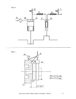
the alignment of compressor and motor. The procedure is shown in Fig.4.
Use vernier callipers or inside micrometer callipers to check the distance (W) (Fig.4). This should be the same
around the whole circumference of the coupling.
Using a micrometer (A), check the radial misalignment between the coupling halves as shown in Fig.4. The
maximum micrometer reading (A) should be as illustrated in Fig. 4.
Even if the unit has been installed on vibration dampers, an alignment check is to be recommended after
installation.
Piping should be so installed that there is no risk of water pockets.
Other equipment should not be installed around the compressor unit in such a way that inspection and
maintenance operations may be hampered.
3.2. Cooling water systems
It is of the greatest importance to the operation and life of the compressor that a good and reliable supply of
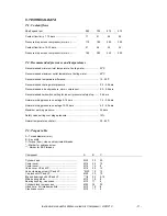
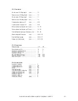
cooling water is ensured. The quantities of cooling water required are given in Table T.1. These specifications
apply to both seawater and freshwater cooling.
Whether the compressor is connected to a central cooling system or has its own separate cooling water pump, it
is important to ensure that the cooling water is circulating properly. In this connection it is not sufficient simply to
check that the compressor pressure gauge is registering cooling water pressure.
If the cooling water feed temperature is too low, increased internal condensation may result. If this is the case,
the cooling water temperature should be increased. If the temperature cannot be increased by recirculation,
condensation can be reduced by reducing the supply of cooling water.
The cylinder block cooling jacket is equipped with a thermometer for the monitoring of cooling water temperature.
Recommended cooling water temperatures are given in Table T.2
.
Содержание HV2/210
Страница 16: ...Fig 1 Instruction manual for Water cooled Air Compressor HV2 210 15...
Страница 17: ...Instruction manual for Water cooled Air Compressor HV2 210 16...
Страница 18: ...Instruction manual for Water cooled Air Compressor HV2 210 17...
Страница 19: ...Instruction manual for Water cooled Air Compressor HV2 210 18...


