


to minimize IGBT switching losses and to reduce EMI noise that might be produced by the
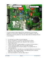
High Power Switching power supply. The IGBT’s are mounted on the heat sink and located
between the IGBT’s , mounted directly on the heat sink is a thermal switch that monitors the
temperature of the inverter plate. If heat temperature exceeds 80 deg C, Over Temp Fault
will occur.
The inverter modules drive the HV transformer T1, which is located near the HV assembly.
6.4.
Filament Inverter/Feedback (460158-XXX)
6.4.1.
Filament Inverter
The Filament Inverter uses two IGBTs in a half bridge configuration to drive filament
transformers Small or Large Filament located on the HV Assembly. The Filament
Inverter uses the same PWM technique as the HV Inverter but in this case it’s hard
switching. The IGBT’s are driven by the PWM located on Filament /Feedback board via
the Gate Driver Transformer. Filament Inverter current is monitored on the primary side
of Filament Transformers using Current Transformer and a RMS converter that is
calibrated to provide actual filament current that is scaled 10VDC= maximum specified
Amps. If Filament Current fails to be regulated to the programmed Filament current,
Filament regulation error will occur and a filament fault will be issued by the DSP.
Filament selection L/S is monitored by a filament confirm signal to the DSP and if
filament selected is not equivalent to confirm signal, the DSP will issue Filament Fault.
6.4.2.
kV and mA Feedback
The Low End 460158-XXX PWB includes kV and mA Feedback Calibration circuitry and
Arc Detector circuit. The kV and mA Feedback Signals are scaled to 10VDC each that
represents full-scale value for nominal output voltage and current. The Filament
Inverter/Feedback PWB receives arcs and kV and mA feedback signals from the High
Voltage Section and sends arcs and calibrated feedback signals to the System Control
board. ICs U1 and U2 are used for calibration of voltage and current feedback signals.
The Arc Detector, Current Transformer T1, detects arcs in the Load or in the HV Section
and then it’s rectified by CR2, which provides an arc pulse to the system control.
XRV SERIES
Page 25
118116-001 REV C