background image

X2364 MANUAL 

118044-001  REV E 


Chapter 4 

P

RINCIPLES 

O

O

PERATION

he X2364 high voltage power supply utilizes 
sophisticated power conversion technology.  A 
variety of analog, digital and power conversion 

techniques are used throughout.  The intention of the 
Principles of Operation is to introduce the basic function 
blocks that comprise the X2364 power supply.  For details 
on a specific circuit, consult Spellman’s Engineering 
Department. 

See Table 4.1 for a list of the main assemblies found in 
the X2364 power supply. 

The X2364 power supply is basically an AC to DC 
converter.  Within the power supply, conversions of AC 
to DC, then high frequency AC, then to high voltage DC 
take place.  By reviewing further the sub-assemblies, a 
basic understanding of the process can be gained. 

4.1  Chassis 

The X2364 is a compact, high efficiency, high voltage 
power supply.  The power supply can supply up to 400 
watts of DC power.  Output voltages of up to 60kV can be 
generated. 

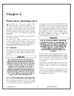
WARNING 

The energy levels used and generated by the 

power supply can be lethal!  Do not attempt to 

operate the power supply unless the user has a 

sufficient knowledge of the dangers and hazards 

of working with high voltage.  Do not attempt to 

approach or touch any internal or external 

circuits or components that are connected or 

have been connected to the power supply.  Be 

certain to discharge any stored energy that may 

be present before and after the power supply is 

used.  Consult IEEE recommended practices for 

safety in high voltage testing #510-1983. 


4.2  Line Rectification and Filtering 

Basic single-phase rectification provides the DC voltage 
for the high frequency inverter.  The line input voltage 
can vary from 187 up to 264 volts within the X2364. 

Circuit protection is provided by CB1 (SYSTEM BLOCK 
DIAGRAM).  CB1 is a fast acting magnetic trip type 
circuit breaker.  The line input is connected directly to the 
line side of CB1.  The load side of CB1 is connected to 
the CONTROL/POWER PWB.  The load side of CB1 is 
also connected to T1 and, via. the HV ON/OFF relay to 
the Remote Cooling Control socket.  T1 is a step-down 
type line transformer.  T1 provides voltage for 
housekeeping and control circuit power. 

WARNING 

LINE VOLTAGE IS PRESENT WHENEVER 

THE POWER SUPPLY IS CONNECTED TO 

EXTERNAL LINE VOLTAGES.  BE SURE TO 

DISCONNECT THE LINE CORD BEFORE 

OPENING THE UNIT.  ALLOW 5 MINUTES 

FOR INTERNAL CAPACITANCE TO 

DISCHARGE BEFORE REMOVING ANY 

COVER. 

When CB1 is ON, voltage is applied to CR10.  CR10 is 
an isolated diode rectifier bridge that contains the rectifier 
diodes used for line voltage rectification.  The output of 
CR10 is connected to a capacitor filter (C11 through 
C14).  Capacitors are initially charged through resistive 
inrush limiters. 

Approximately 1 second after CB1 is turned on, a relay is 
energized to short the resistor limiters.  This relay is K1.  
This DC voltage is supplied to the high frequency 
inverter. 

The DC rails are connected to the high frequency rail 
capacitors.  These capacitors are high frequency, low loss 
type.  Capacitors C21 and C22 provide the energy storage 
for the high frequency inverter.

Содержание XLG60P400/X2364

Страница 1: ...SERIAL DATE SPELLMAN HIGH VOLTAGE ELECTRONICS CORPORATION 475 Wireless Blvd Hauppauge New York 11788 1 631 630 3000 FAX 1 631 435 1620 E mail sales spellmanhv com Website www spellmanhv com X2364 MANUAL 118045 001 Rev C XLG60P400 X2364 ...

Страница 2: ... aware of the electrical hazards WARNING note in the text call attention to hazards in operation of these units that could lead to possible injury or death CAUTION notes in the text indicate procedures to be followed to avoid possible damage to equipment Copyright 2000 Spellman High Voltage Electronics Corporation All Rights Reserved This information contained in this publication is derived in par...

Страница 3: ...spannungsnetzteiles benötigen ca 5 Minuten um sich zu entladen Erden Sie sich nicht und arbeiten Sie nicht in feuchter oder nasser Umgebung Notwendige Reparaturen können es erforderlich machen den Gehäusedeckel während des Betriebes zu entfernen Reparaturen dürfen nur von qualifiziertem eingewiesenem Personal ausgeführt werden WARNING im folgenden Text weist auf gefährliche Operationen hin die zu ...

Страница 4: ...de l alimentation Ne vous mettez pas à la masse ou ne travaillez pas sous conditions mouillées ou humides La maintenance peut nécessiter l enlèvement du couvercle lorsque l alimentation est encore allumée Les réparations doivent être effectuées par une personne qualifiée et connaissant les risques électriques Dans le manuel les notes marquées WARNING attire l attention sur les risques lors de la m...

Страница 5: ...carica della capacità interna dell alimentatore ad alta tensione Non mettere a terra il proprio corpo oppure operare in ambienti bagnati o saturi d umidità SICUREZZA NELLA MANUTENZIONE Manutenzione potrebbe essere richiesta rimuovendo la copertura con apparecchio acceso La manutenzione deve essere svolta da personale qualificato coscio dei rischi elettrici Attenzione alle AVVERTENZE contenute nel ...

Страница 6: ...sis 9 4 2 Line Rectifier and Filtering 9 4 3 Inverter 10 4 4 High Voltage Transformer 10 4 5 High Voltage Assembly 10 4 6 Control Power PWB 10 4 7 Front Panel Assembly 11 4 8 Filament Supply PWB 11 5 MAINTENANCE 5 1 Periodic Servicing 12 5 2 Performance Test 12 5 3 High Voltage Dividers 12 6 REPLACEMENT PARTS 6 1 Replacement Parts 13 6 2 Correspondence and Ordering Spare Parts 13 7 FACTORY SERVICE...

Страница 7: ...D ILLEGAL COMMANDS 22 8 5 COMMAND SUMMARY 23 APPENDIX A Specification Controls LIST OF FIGURES Figure 2 1 Dimensions X2364 4 Figure 3 1 Typical Operating Setup X2364 7 Figure 3 2 Rear Panel I O Interface 8 LIST OF TABLES Table 4 1 List of Main Assemblies 10 Table 8 1 DB 9 Pin Out I O 16 Table 8 2 Relevant ASCII Codes 16 Table 8 3 SET Command Byte Contents 17 Table 8 4 Response Packet Byte Contents...

Страница 8: ... shock and filament shock to the X ray tube The kV ramp rate is approximately 6 seconds The filament current is slowly increased until the desired mA level is achieved This time is typically 5 seconds for full mA output These ramp conditions are started at the initial HV ON control signal ARC DETECT ARC QUENCH ARC COUNT These features allow the user to tailor the power supply to meet specific need...

Страница 9: ...s INTLK OPEN Indicates the EXTERNAL INTERLOCK connections are in the open position This also indicates opening of internal power supply interlocks OVER VOLT Indicates the overvoltage protection circuitry has caused the power supply to turn off Overvoltage protection is internally set to 110 of rated output voltage OVER CURR Indicates the output current has exceeded the preset limit The overcurrent...

Страница 10: ...if damage is evident Do not destroy or remove any of the packing material used in a damaged shipment After unpacking inspect the panel and chassis for visible damage Fill out and mail the Warranty Registration card accompanying the unit Standard Spellman X2364 high voltage power supply and components are covered by warranty 2 2 Mechanical Installation The X2364 has front panel holes for standard E...

Страница 11: ...X2364 MANUAL 4 118044 001 REV E Figure 2 1 X2364 DIMENSIONS ...

Страница 12: ...ontrol fully counter clockwise to the zero voltage position G The input power cable may now be connected to the AC power line H Switch the front panel circuit breaker to the ON position 1 If the supply is to be turned off for an extended period of time the line cord should be disconnected The unit is now in the HIGH VOLTAGE OFF mode The HIGH VOLTAGE OFF light should be lit I Depress and hold the H...

Страница 13: ...t s high voltage inverter will be disabled During high voltage operation opening the interlock circuit will cause the unit to revert to the HIGH VOLTAGE OFF mode Subsequent closing of the interlock circuit will NOT return the unit to HIGH VOLTAGE ON mode this must be accomplished by depressing the HIGH VOLTAGE ON switch See Figure 3 2 for the recommended interface circuit ARC DETECT ARC QUENCH ARC...

Страница 14: ...X2364 MANUAL 7 118044 001 REV E Figure 3 1 Typical Operating Setup X2364 Rear Panel ...

Страница 15: ...erate 15Vdc Return 15Vdc 0 to 50mA max switch is not used Do Not Short Install proper resistor if FAIL SAFE lamp is not used 100 ohms 2W or higher Install jumper if INTERLOCK contacts are not used Install jumper if INTERLOCK contacts are not used Signals are 15Vdc 25mA max and are only to be used for contact closure They should be located as close as possible to the power supply It is recommended ...

Страница 16: ...lt IEEE recommended practices for safety in high voltage testing 510 1983 4 2 Line Rectification and Filtering Basic single phase rectification provides the DC voltage for the high frequency inverter The line input voltage can vary from 187 up to 264 volts within the X2364 Circuit protection is provided by CB1 SYSTEM BLOCK DIAGRAM CB1 is a fast acting magnetic trip type circuit breaker The line in...

Страница 17: ...wer PWB The majority of control circuits for power supply controls are located on the CONTROL POWER PWB 15VDC 15VDC and 10VDC is generated on the CONTROL POWER PWB High Voltage On Off control is accomplished by K3 and its associated circuitry Interlock control is provided by K4 Voltage feedback from the high voltage divider is sent to U9 Gain adjust is provided on the FILAMENT PWB The KV feedback ...

Страница 18: ...OWER PWB 4 8 Filament Supply PWB The power for the X ray tube is provided by the filament inverter The filament inverter is a high frequency series resonant inverter The inverter provides regulated current to the primary of the filament transformer The filament isolation transformer output is then rectified by CR8 and CR9 filtered by C6 through C11 and then connected to the output block terminal T...

Страница 19: ...ge Power Supplies Copies can be obtained from the Spellman Customer Service Department Test equipment including an oscilloscope a high impedance voltmeter and a high voltage divider such as the Spellman HVD 100 or HVD 200 is needed for performance tests All test components must be rated for operating voltage 5 3 High Voltage Dividers High voltage dividers for precise measurements of output voltage...

Страница 20: ...nd serial number of the power supply 6 2 Correspondence And Ordering Spare Parts Each Spellman power supply has an identification label on the rear of the chassis that bears its model and serial number When requesting engineering or applications information please state the model and serial number of the power supply If specific components or circuit sections are involved in the inquiry it is help...

Страница 21: ...rly on the outside of the shipping container Packages received without an RMA Number will be returned to the customer The Customer shall pay for shipping to and from Spellman A preliminary estimate for repairs will be given by phone by Customer Service A purchase order for this amount is requested upon issuance of the RMA Number A more detailed estimate will be made when the power supply is receiv...

Страница 22: ...s To meet our resolution requirements of 0 1 10 bits is the maximum number of bits that can be used 8 1 RS232 Overview RS 232C is used with single ended transmission over relatively short lines The standard defines the electrical characteristics for the interfacing of Data Terminal Equipment DTE and Data Communications Equipment DCE In our case the Customer Computer is the DTE and the Spellman Pow...

Страница 23: ...Data RxD 2 3 Power supply transmit line Transmit Data TxD 3 2 Power supply receive line Data Terminal Ready DTR 4 20 Shorted to pins 1 6 Signal Ground GND 5 7 Signal ground Data Set Ready DSR 6 6 Shorted to pins 1 4 Request to Send RTS 7 4 Shorted to pin 8 Clear To Send CTS 8 5 Shorted to pin 7 Ring Indicator RI 9 22 Not used TABLE 8 1 DB 9 I O PIN OUT ...

Страница 24: ...ontrol 0 FFF hex represents 0 15 milliamperes output Internal to the power supply interface the D A converters have an analog output range of 0 to 10 volts DC where FFF hex represents full scale Digital Control Signals sent from Customer Computer to Spellman Power Supply 1 X ray On 0 off 1 on 2 X ray Off 0 on 1 off This function also provides reset Programming a digital control bit to a 1 will gen...

Страница 25: ...ions are detected by the power supply the command will not be executed and the appropriate 5 byte ERROR E packet will be sent back to the computer 8 2 1 Set Command S and Acknowledge A Response Prior to sending a Set Command that performs any function other than a Power Supply Reset the computer should ensure that no fault conditions are existing within the power supply This is done by first sendi...

Страница 26: ...it resolution is FFF hex 33 000 volts is therefore represented as 8CC hex within an error of 1 lsb Bytes 3 5 will be sent containing the ASCII representation of 8CC enter 8CC at the computer keyboard Byte 3 38 hex 0011 1000 binary Byte 4 43 hex 0100 0011 binary Byte 5 43 hex 0100 0011 binary Byte 6 through 8 represents the current 3 75 milliamperes is 25 of full scale Full scale 15mA with 12 bit r...

Страница 27: ...mmand several checks are made If an illegal condition is detected the command will not be executed and an error message will be sent back to the computer The conditions that are checked are described in Section 8 4 Errors of this document If no errors are detected the data interface will execute the command and then send a 2 byte Acknowledge Packet back to the computer The format of the Acknowledg...

Страница 28: ...er supply will return the 6 byte Version Response B packet back to the computer If errors are detected in the V command the power supply will return an appropriate error message The format of the V command is SOH V Check 1 Check 2 CR Entered at the keyboard Ctrl A V 6 Enter Sent in ASCII coded hexadecimal 01 56 35 36 0D where the checksum which does not include the SOH character will be hex 56 tra...

Страница 29: ... character of the received command packet is not an S Q or V The error packet that will be returned to the computer will be Characters sent E 2 3 2 CR Sent in ASCII coded hexadecimal 45 33 33 32 0D 3 Checksum Error the transmitted checksum received in the command packet did not match the checksum calculated on the received bytes The error packet that will be returned to the computer will be Charac...

Страница 30: ...ds from the computer to the power supply are S Set Power Supply contains desired power supply settings 18 bytes Q Query Power Supply requests that the power supply returns to the computer a Response Packet 5 bytes V Request Power Supply Software Version Level 5 bytes Responses from the power supply back to the computer start with an A R E or B character A Acknowledge Response Packet 2 bytes R Data...

Страница 31: ...To obtain information on Spellman s product warranty please visit our website at http www spellmanhv com en About Warranty aspx ...

Отзывы: