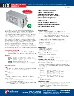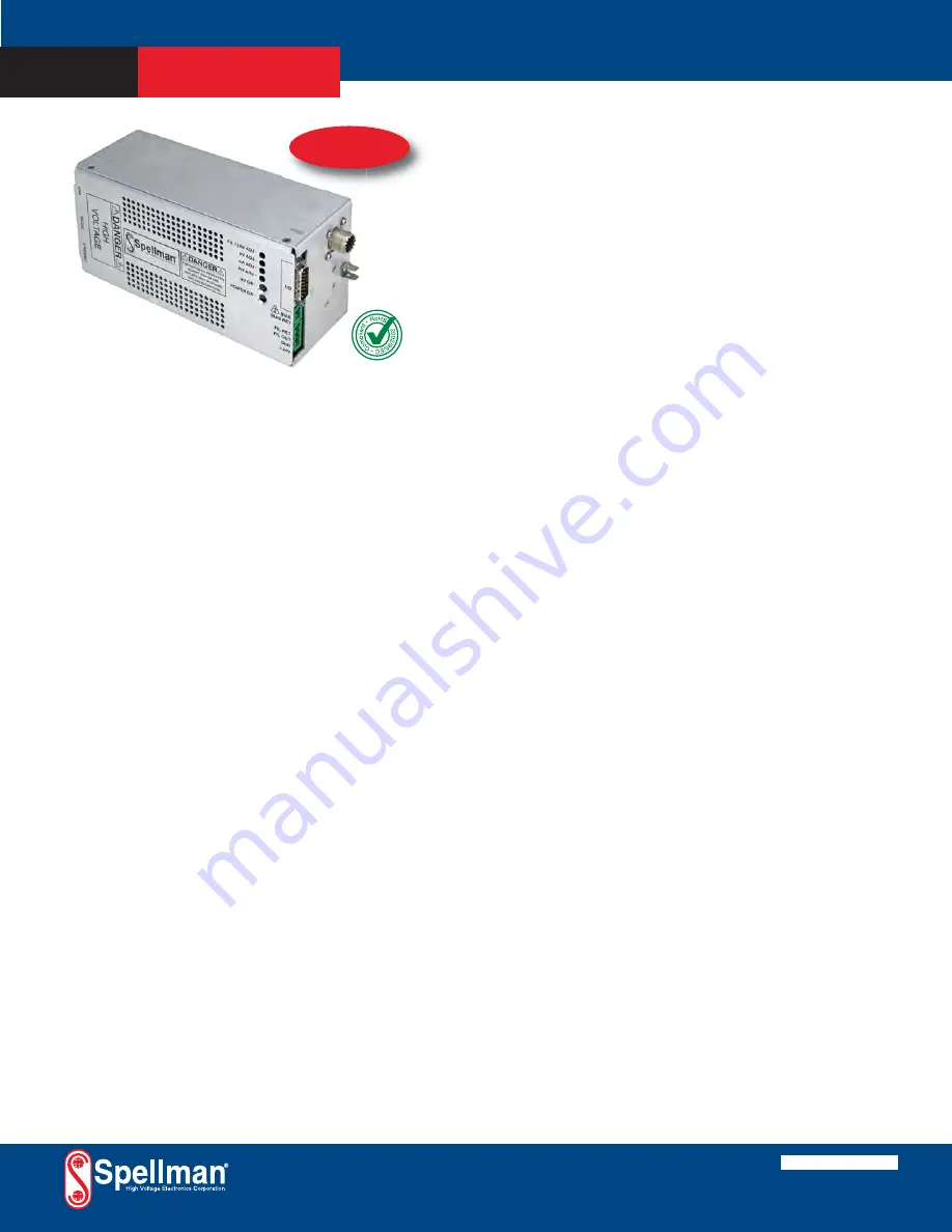
The uX Series is the result of Spellman’s exceptional
high voltage packaging and surface mount fabrication
techniques coupled with proprietary encapsulation
technology producing this ultra-compact X-Ray generator
module. The uX powers grounded cathode X-Ray tubes
from a variety of well-known manufacturers, featuring a
0 to 50kV/65kV high voltage output @ 2mA limited to 50,
65 or 75 Watts. The uX uses closed loop filament control
circuitry providing highly regulated beam current. The low
noise dc filament supply operates between 0.3 and 3.5
amps. Offering tight regulation, high stability and low
ripple, the uX provides users local and remote analog
control to set beam voltage, emission current and filament
current limit. USB, RS-232 and Ethernet interface is standard.
TYPICAL APPLICATIONS
Powering grounded cathode X-Ray tubes from
Kevex, Oxford, RTW, Superior, Varian and Trufocus.
OPTIONS
XCC
XRM Compatible HV Cable (50kV only)
5VPM
0 to 5 Volt Programming and Monitor Scaling
GB
Grid Bias Option
K5302
Mammoflex HV cable for uX
K2001
Mammoflex HV cable for uX w/XCC option
SPECIFICATIONS
Input:
+24Vdc ±10%, 5.0A maximum for either 50 Watts or 75 Watts.
+24Vdc ±1V, 5.0A maximum for 65kV/65W units.
Efficiency:
75%, typical
Output:
0 to 50kV at 0 to 2mA, limited to a maximum of 50 wattsr
or 75 Watts. 0-65kV at 2mA limited to 65 Watts.
Voltage Control:
Local: Internal multi-turn potentiometer to set voltage
from 0 to full output voltage.
Remote: 0 to +10Vdc proportional from 0 to full output voltage.
Accuracy: ±1%. Z
IN
: 10Mohm.
Emission Control:
Local: Internal potentiometer to set beam current
between 0 and full output current.
Remote: 0 to +10Vdc proportional from 0 to full output current.
Accuracy: ±1%. Z
IN
: 10Mohm. Filament limit and
filament preheat control capability is also provided.
DC Filament Supply:
Islolated filament power supply generates emission
current feedback signal for accurate low X-Ray tube
current performance.
Current: 3.5A, adjustable limit
Voltage: 5.0 volt limit
Environmental:
Operational: 0°C to +50°C
Storage: -40°C to +85°C
Humidity: 0% to 90%, non-condensing
Temperature Coefficient:
0.01% per °C, voltage and current.
Stability:
0.05% per 8 hours after 1/2 hour warm-up.
Voltage and Current Monitors:
0 to +10Vdc proportional from 0 to rated output. Accuracy ±1%.
Redundant Voltage Monitor:
A redundant high voltage feedback divider with proportional
0 to +10Vdc = 0 to 100% output voltage signal can be provided
on a custom basis.
Dimensions:
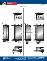
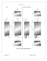
50kV Unit: 4.00”H x 2.87”W x 8.00”D
(101.6mm x 72.95mm x 202.20mm).
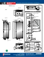
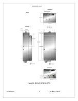
65kV Unit: 4.00”H x 2.87”W x 9.00”D
(101.6mm x 72.95mm x 228.60mm).
XCC Option: 4.00”H x 2.87”W x 9.00”D
(101.6mm x 72.95mm x 228.60mm).
Weight:
4.5 lbs. (2.1kg) typical
Regulatory Approvals:
Compliant to 2004/108/EC, the EMC Directive and 2006/95/EC,
the Low Voltage Directive (approval pending). UL/CUL
recognized, File E227588 (approval pending). Compliant to
2002/95/EC, RoHS.
•
50kV at 2 mA. 50 or 75 Watt Max.
•
65kV at 2 mA. 65 Watt Max.
•
Adjustable Isolated Filament Supply
•
Overvoltage & Short Circuit Protection
•
Voltage & Current Programming
•
Local and Remote Emission Control
•
Safety Interlock
•
RS-232, Ethernet, & USB Standard
•
Redundant HV Monitor Signal Available
•
OEM Customization Available
SPELLMAN HIGH VOLTAGE ELECTRONICS CORPORATION
u
X
50W/65W/75W X-RAY
GENERATOR
PAGE 1 OF 5
30% Smaller
than MNX
Corporate Headquarters
Hauppauge, New York USA
+1-631-630-3000 FAX: +1-631-435-1620
e-mail: [email protected]
www.spellmanhv.com
128108-001 REV. A
Spellman High Voltage is an ISO 9001:2008 and ISO 14001:2004 registered company
Copyright © 2014 Spellman High Voltage Electronics Corp.
Содержание uX50P50
Страница 16: ...uX MANUAL 4 118151 001 REV A Figure 2 1 50kV uX DIMENSIONS ...
Страница 17: ...uX MANUAL 5 118151 001 REV A Figure 2 2 65kVuX DIMENSIONS ...
Страница 21: ...uX MANUAL 9 118151 001 REV A Table 3 2 DC Input Filament Connections ...
Страница 22: ...uX MANUAL 10 118151 001 REV A Figure 3 3 Monitors Voltage Current Control Connections ...
Страница 23: ...uX MANUAL 11 118151 001 REV A Figure 3 4 Recommended Interlock HV on Configurations ...

