uX MANUAL
13
118151-001 REV A
4.3 High Voltage Transformer
The output of the High Frequency Resonant Inverter is
connected to the primary of the High Voltage
Transformer. The High Voltage Transformer is a step-up
type. Typically secondary voltages are in the range of
5kV depending upon output voltage ratings.
4.4 High Voltage Assembly
The High Voltage Assembly will vary depending upon
the model ordered. The circuitry typically consists of
series arrangements of a half wave voltage multiplier.
The higher voltage ranges utilize various series
arrangements of a voltage doubler.
Output filtering is typically provided by an R-C type
filter. A high bandwidth resistive/capacitive divider
provides voltage feedback for regulation and monitoring.
Current feedback for regulation and monitoring is
provided by a sense resistor connected at the low voltage
end of the High Voltage Rectifier/Multiplier Circuit.
4.5 Control PWB
The majority of control circuits for power supply controls
are located on the CONTROL/POWER PWB.
+15VDC, -15VDC, and +10VDC are generated on the
CONTROL/POWER PWB. High Voltage On/Off control
is accomplished by K2, and its associated circuitry.
Interlock control is provided by K2.
Voltage feedback from a high voltage divider, located on
the High Voltage Assembly, is sent to U16. Gain
adjustment is provided by R98. The KV feedback signal
is sent to the 15 pin D connector for remote monitoring.
Program voltages are typically ramped up to set level by
the slow start circuits of U16.
Current feedback from the high voltage rectifier is sent to
sense resistors located on the High Voltage Assembly.
Feedback is then sent to U15.
The resonant control circuitry consists of a voltage to
pulse width converter. U17 generates all pulse width
control signals.
4.6 Filament Supply
The filament inverter provides the power for the X-ray
tube filament. The filament inverter is a high frequency
inverter. The inverter provides regulated current to the
primary of the filament transformer. The filament
isolation transformer secondary is then connected to the
output connector.
4.7 Options
Due to the many variations of models and options
provided in the uX series, details of actual circuits used
may differ slightly from above descriptions. Consult
Spellman’s Engineering Department for questions
regarding the principles of operations for the uX series.
Содержание uX50P50
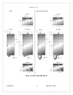
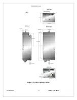
Страница 16: ...uX MANUAL 4 118151 001 REV A Figure 2 1 50kV uX DIMENSIONS ...
Страница 17: ...uX MANUAL 5 118151 001 REV A Figure 2 2 65kVuX DIMENSIONS ...
Страница 21: ...uX MANUAL 9 118151 001 REV A Table 3 2 DC Input Filament Connections ...
Страница 22: ...uX MANUAL 10 118151 001 REV A Figure 3 3 Monitors Voltage Current Control Connections ...
Страница 23: ...uX MANUAL 11 118151 001 REV A Figure 3 4 Recommended Interlock HV on Configurations ...

