background image

uX MANUAL 

12 

118151-001  REV A 

Chapter 4 

Principles of Operation

he uX series of modular X-ray generators utilizes 
sophisticated power conversion technology.  A 
variety of analog, digital and power conversion 

techniques are used throughout.  The intention of the 
Principles of Operation is to introduce the basic function 
blocks that comprise the uX power supply.  For details on 
a specific circuit, consult Spellman’s Engineering 
Department. 

The uX power supply is basically a DC-to-DC converter.  
Within the power supply, conversions of DC to high 
frequency AC, then to high voltage DC takes place.  By 
reviewing further the sub-assemblies, a basic 
understanding of the process can be gained. 

WARNING 

To reduce the risk of fire, replace fuse with same type and 

rating. 


WARNING 

Um die Brandgefahr zu verringern, muss die Sicherung 

durch eine neue gleichen Typs ersetzt werden. 

4.1 Chassis 

The uX is a compact, high efficiency, X-ray generator.  
The power supply can supply up to 75 watts of DC power.  
(Output power capability may be higher or lower 
depending upon model ordered).  Output voltages of up to 
65kV can be generated. 

WARNING 

The energy levels used and generated by the 

power supply can be lethal!  Do not attempt to 

operate the power supply unless the user has a 

sufficient knowledge of the dangers and hazards 

of working with high voltage.  Do not attempt to 

approach or touch any internal or external 

circuits or components that are connected or 

have been connected to the power supply.  Be 

certain to discharge any stored energy that may 

be present before and after the power supply is 

used.  Consult IEEE recommended practices for 

safety in high voltage testing #510-1983. 


WARNUNG 

Die verwendete und erzeugte Engergie des 

Hochspannungsnetzteiles kann tötlich sein!  Betreiben Sie 

das Hochspannungsnetzeil nur wenn Sie ausreichendes 

Kenntnis über mögliche Gefahren beim Ungang mit der 

Hochspannung haben.  Versuchen Sie nicht interne 

Schaltkreise oder elektrische Bauelemente, die an das 

Hochspannungsnetzteil angeschlossen sind, zu berühren.  

Vergewissern Sie sich, daß alle Restladungen, die vor 

oder nacj dem Betreib des Hochspannungsnetzteils 

vrhanden sind, entladen werden.  Weitere Informationen 

finden Sie der IEEE-Vorschrift Nr. 510-1983. 

4.2 Inverter 

The inverter is a series resonant, parallel loaded topology.  
A PWM scheme is used for regulating the power 
generated from the inverter.  Q1 is a high speed 
MOSFET.  This device provides high frequency 
switching to control the resonant current flow.  The 
typical resonant operating period is approximately 15

μ


seconds.  

Содержание uX50P50

Страница 1: ...n Manual High Voltage Power Supply MODEL SERIAL DATE SPELLMAN HIGH VOLTAGE ELECTRONICS CORPORATION 475 Wireless Blvd Hauppauge New York 11788 1 631 630 3000 FAX 1 631 435 1620 E mail sales spellmanhv com Website www spellmanhv com uX SERIES ...

Страница 2: ... Accuracy 1 ZIN 10Mohm Filament limit and filament preheat control capability is also provided DC Filament Supply Islolated filament power supply generates emission current feedback signal for accurate low X Ray tube current performance Current 3 5A adjustable limit Voltage 5 0 volt limit Environmental Operational 0 C to 50 C Storage 40 C to 85 C Humidity 0 to 90 non condensing Temperature Coeffic...

Страница 3: ...y two position Phoenix Contact terminal block the mating connecter is provided GRID BIAS SPECIFICATIONS Output Voltage 0 to 300Vdc Output Current 0 25mA maximum Load Regulation 1 of output voltage no load to full load Line Regulation 1 for a 10 change in input voltage Ripple 1 of maximum rated voltage uX with Grid Bias Option Shown with Oxford Apogee X Ray Tube not included Note Units ordered with...

Страница 4: ...e cable is provided SHV p n 201946 007 K2001 A one meter 39 4 long Mammoflex mating high voltage cable is provided compatible with the XCC Option SHV p n 201946 002 GRID BIAS CONNECTOR 2 PIN PHOENIX CONTACT PIN SIGNAL PARAMETER 1 Ground Chassis Ground 2 Grid Bias 0 to 300Vdc How To Order Sample model number 50 Watt unit uX50P50 65 Watt unit uX65P65 75 Watt unit uX50P75 Options are added to the mod...

Страница 5: ...R 50KV 50KV WITH XCC OPTION Corporate Headquarters Hauppauge New York USA 1 631 630 3000 FAX 1 631 435 1620 e mail sales spellmanhv com www spellmanhv com 128108 001 REV A Spellman High Voltage is an ISO 9001 2008 and ISO 14001 2004 registered company Copyright 2014 Spellman High Voltage Electronics Corp ...

Страница 6: ... ON Relay Relay Return Grounded EXTERNAL INTERLOCK 24VDC 24V Power To HV Circuits CURRENT MONITOR FILAMENT MONITOR FILAMENT LIMIT SETPOINT FILAMENT PREHEAT SETPOINT EXTERNAL CURRENT CONTROL EXTERNAL VOLTAGE CONTROL V V M M M M M Jumper J4 7 to J4 8 to Use Local Voltage Control Jumper J4 10 to J4 11 to Use Local Current Control LOCAL VOLTAGE CONTROL 10 00V REFERENCE 10 00V 10 00V 10 00V 10 00V 10 0...

Страница 7: ... aware of the electrical hazards WARNING note in the text call attention to hazards in operation of these units that could lead to possible injury or death CAUTION notes in the text indicate procedures to be followed to avoid possible damage to equipment Copyright 2000 Spellman High Voltage Electronics Corporation All Rights Reserved This information contained in this publication is derived in par...

Страница 8: ...spannungsnetzteiles benötigen ca 5 Minuten um sich zu entladen Erden Sie sich nicht und arbeiten Sie nicht in feuchter oder nasser Umgebung Notwendige Reparaturen können es erforderlich machen den Gehäusedeckel während des Betriebes zu entfernen Reparaturen dürfen nur von qualifiziertem eingewiesenem Personal ausgeführt werden WARNING im folgenden Text weist auf gefährliche Operationen hin die zu ...

Страница 9: ...de l alimentation Ne vous mettez pas à la masse ou ne travaillez pas sous conditions mouillées ou humides La maintenance peut nécessiter l enlèvement du couvercle lorsque l alimentation est encore allumée Les réparations doivent être effectuées par une personne qualifiée et connaissant les risques électriques Dans le manuel les notes marquées WARNING attire l attention sur les risques lors de la m...

Страница 10: ...carica della capacità interna dell alimentatore ad alta tensione Non mettere a terra il proprio corpo oppure operare in ambienti bagnati o saturi d umidità SICUREZZA NELLA MANUTENZIONE Manutenzione potrebbe essere richiesta rimuovendo la copertura con apparecchio acceso La manutenzione deve essere svolta da personale qualificato coscio dei rischi elettrici Attenzione alle AVVERTENZE contenute nel ...

Страница 11: ...tures 7 4 PRINCIPLES OF OPERATION 4 1 Chassis 12 4 2 Inverter 12 4 3 High Voltage Transformer 13 4 4 High Voltage Assembly 13 4 5 Control PWB 13 4 6 Filament Supply 13 4 7 Options 13 5 OPTIONS 5 1 XCC Option 14 5 2 5VPM 14 5 3 GB 14 5 4 K5302 14 5 5 K2001 14 563 Custom Designed Models 14 6 MAINTENANCE 6 1 Periodic Servicing 15 6 2 Performance Test 15 6 3 High Voltage Dividers 15 7 REPLACEMENT PART...

Страница 12: ...ols Custom Models Only LIST OF FIGURES Figure 2 1 Dimensions 50kV uX 4 Figure 2 2 Dimensions 65kV uX 5 Figure 3 1 Typical Operating Setup uX 8 Figure 3 2 DC Input Filament Connections 9 Figure 3 3 Monitors Voltage Current Control Connections 10 Figure 3 4 Recommended Interlock HV on Connections 11 LIST OF TABLES Table 1 1 Options 2 ...

Страница 13: ... ripple provides higher intensity levels with no increase in tube loading All these advancements are possible only by Spellman s long history in X ray power systems This series of power supplies utilize extremely advanced resonant conversion techniques along with sophisticated digital technology The uX series is specifically designed for X ray tube application where the high voltage is a positive ...

Страница 14: ...are provided on the Analog Interface connector on the front of the chassis for connection to a safety switch The unit will not operate unless the interlock circuit is closed The recommended configuration is to close the interlock circuit through a 12V lamp rated for 0 5W to 0 8W and a safety switch This configuration provides fail safe interlocking During high voltage operation opening the safety ...

Страница 15: ...ndard Spellman uX X Ray generators are covered by warranty Custom and special order models with an X suffix in the model number are also covered by warranty 2 2 Mechanical Installation The uX Series of modular X ray generators are designed for installation into existing or newly developed OEM equipment The X ray generator can also easily fit into bench top applications or test set requirements Sta...

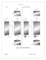
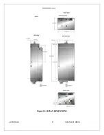
Страница 16: ...uX MANUAL 4 118151 001 REV A Figure 2 1 50kV uX DIMENSIONS ...

Страница 17: ...uX MANUAL 5 118151 001 REV A Figure 2 2 65kVuX DIMENSIONS ...

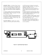
Страница 18: ... preferably to a water system ground using copper pipe or other earth ground using the connection terminal at the rear of the unit See Figure 3 1 for a typical operating setup The return line from the load should be connected to the terminal on the rear of the power supply Using a separate external ground at the load is not recommended C Attach the output cable to the load D Plug the high voltage ...

Страница 19: ...al or remote adjustment of the output voltage and current Adjustments are made using the screwdriver adjustable potentiometers accessible through the top cover of the power supply or via an external voltage source provided by the operator In local control jumpers are installed on the 15 pin interface connector between pin 7 and pin 8 for voltage control and between pin 10 and pin 11 for current co...

Страница 20: ...applied to the unit and the Interlock is Open High Voltage OFF The Preheat Level is adjustable from between 8A to 2 5A Selecting the correct preheat current level can greatly reduce or eliminate the overshoot that typically occurs on the output emission current when operating into a cold filament The Preheat adjustment is made when the power supply is in the high voltage OFF mode Interlock Open vi...

Страница 21: ...uX MANUAL 9 118151 001 REV A Table 3 2 DC Input Filament Connections ...

Страница 22: ...uX MANUAL 10 118151 001 REV A Figure 3 3 Monitors Voltage Current Control Connections ...

Страница 23: ...uX MANUAL 11 118151 001 REV A Figure 3 4 Recommended Interlock HV on Configurations ...

Страница 24: ...an be lethal Do not attempt to operate the power supply unless the user has a sufficient knowledge of the dangers and hazards of working with high voltage Do not attempt to approach or touch any internal or external circuits or components that are connected or have been connected to the power supply Be certain to discharge any stored energy that may be present before and after the power supply is ...

Страница 25: ... PWB High Voltage On Off control is accomplished by K2 and its associated circuitry Interlock control is provided by K2 Voltage feedback from a high voltage divider located on the High Voltage Assembly is sent to U16 Gain adjustment is provided by R98 The KV feedback signal is sent to the 15 pin D connector for remote monitoring Program voltages are typically ramped up to set level by the slow sta...

Страница 26: ... current programming inputs and monitors to 0 5V 0 full rated output 5 3 Grid Bias Option GB Plug n play compatibility for Oxfords Apogee X ray tubes that utilize grid bias control 5 4 Mammoflex HV Cable K5302 Mammoflex HV cable for uX 5 5 Mammoflex HV Cable K2001 Mammoflex HV cable for uX with XCC option 5 6 Custom Designed Models X Units built to customer specifications are assigned an X number ...

Страница 27: ...tage test procedures are described in Bulletin STP 783 Standard Test Procedures for High Voltage Power Supplies Copies can be obtained from the Spellman Customer Service Department Test equipment including an oscilloscope a high impedance voltmeter and a high voltage divider such as the Spellman HVD 100 or HVD 200 is needed for performance tests All test components must be rated for operating volt...

Страница 28: ...nd serial number of the power supply 7 2 Correspondence and Ordering Spare Parts Each Spellman power supply has an identification label on the rear of the chassis that bears its model and serial number When requesting engineering or applications information please state the model and serial number of the power supply If specific components or circuit sections are involved in the inquiry it is help...

Страница 29: ... to the customer The Customer shall pay for shipping to and from Spellman A preliminary estimate for repairs will be given by phone by Customer Service A purchase order for this amount is requested upon issuance of the RMA Number A more detailed estimate will be made when the power supply is received at the Spellman Repair Center In the event that repair work is extensive Spellman will call to see...

Страница 30: ...ged breach of this warranty No modification amendment supplement addition or other variation of this warranty will be binding unless it is set forth in a written instrument signed by an authorized officer of Spellman Factory Service Procedures For an authorization to ship contact Spellman s Customer Service Department Please state the model and serial numbers which are on the plate on the rear pan...

Отзывы: