SLS SERIES MANUAL
11
118132-001 RevA
J3
SIGNAL
SIGNAL PARAMETERS
1
Power Supply Common
Signal Ground
2
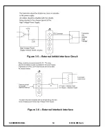
External Inhibit
Ground = Inhibit, Open = HV ON
3
External Interlock
+15V at Open, <15mA at Closed
4
External Interlock Return
Return For External Interlock
5
Current Monitor
0 to 10V = 0 to 100% Rated Output
6
kV Test Point
0 to 10V = 0 to 100% Rated Output
7
+10V Reference
+10.24V, 1mA Max
8
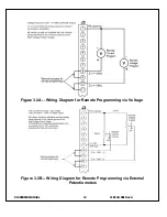
Remote Current Program In
0 to 10V = 0 to 100% Rated Output
9
Local Current Program Out
Front Panel Program Voltage
10
Remote Voltage Program In
0 to 10V = 0 to 100% Rated Output
11
Local Voltage Program Out
Front Panel Program Voltage
12
EFR (Common)
Optional External Fault Relay
13
EFR (Normally Open)
Optional External Fault Relay
14
Local HV Off Out
+15V at Open, < 25mA at Closed.
Connect to HV OFF For FP Operation
15
HV OFF
15V at Open, < 25mA at Closed.
Connect to Local HV Off Out For FP Operation
16
Remote HV ON
+15V, 10mA Max = HV ON
17
Remote HV OFF Indicator
0 = HV ON, +15V, 10mA Max = HV OFF
18
Remote HV ON Indicator
0 = HV OFF, +15V, 10mA Max = HV ON
19
Remote Voltage Mode
Open Collector 50V Max, 10mA Max On = Active
20
Remote Current Mode
Open Collector 50V Max, 10mA Max On = Active
21
spare
spare
22
Remote PS Fault
0 = Fault, +15V, 0.1 Ma Max = No Fault
23
+15V Output
+15V, 100mA Max
24
Power Supply Common
Signal Ground
25
Shield Return
Chassis Ground
Table 3.2 - Rear Panel Interface 25 pin Mini D
Содержание SLS SERIES
Страница 16: ...SLS SERIES MANUAL 6 118132 001 RevA Figure 2 1 SLS Series Typical Dimensions SLS180P2000 shown ...
Страница 25: ...SLS SERIES MANUAL 15 118132 001 RevA Figure 3 7 Remote High Voltage On and Remote High Voltage off Indicator ...
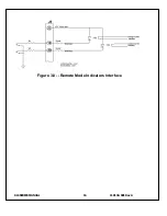
Страница 26: ...SLS SERIES MANUAL 16 118132 001 RevA Figure 3 8 Remote Mode Indicators Interface ...

