background image

101520-007   REV D 

SPELLMAN HIGH VOLTAGE ELECTRONICS 

WARRANTY


Spellman

 High Voltage Electronics 

(“Spellman”)

 warrants that all power supplies it manufactures will be 

free from defects in materials and factory workmanship, and agrees to repair or replace, without charge, any 
power supply that under normal use, operating conditions and maintenance reveals during the warranty 
period a defect in materials or factory workmanship.   The warranty period is twelve (12) months from the 
date of shipment of the power supply. With respect to standard SL power supplies (not customized) the 
warranty period is thirty-six (36) months from the date of shipment of the power supply. 


This warranty does not apply to any power supply that has been: 


Disassembled, altered, tampered, repaired or worked on by persons unauthorized by 

Spellman;


subjected to misuse, negligent handling, or accident not caused by the power supply; 


installed, connected, adjusted, or used other than in accordance with the original intended application and/or 
instructions furnished by 

Spellman.


THE FOREGOING WARRANTY IS IN LIEU OF ALL OTHER WARRANTIES, EXPRESS OR IMPLIED, INCLUDING 
THOSE OF MERCHANTABILITY OR FITNESS FOR A PARTICULAR PURPOSE.  


The buyer’s sole remedy for a claimed breach of this warranty, and 

Spellman’s 

sole liability is limited, at 

Spellman’s

 discretion, to a refund of the purchase price or the repair or replacement of the power supply at 

Spellman’s

 cost.   The buyer will be responsible for shipping charges to and from 

Spellman’s

 plant.   The 

buyer will not be entitled to make claim for, or recover, any anticipatory profits, or incidental, special or 
consequential damages resulting from, or in any way relating to, an alleged breach of this warranty. 


No modification, amendment, supplement, addition, or other variation of this warranty will be binding unless 
it is set forth in a written instrument signed by an authorized officer of 

Spellman. 


Factory Service Procedures 


For an authorization to ship contact 

Spellman’s

 Customer Service Department. Please state the model and 

serial numbers, which are on the plate on the rear panel of the power supply and the reason for return.  A 
Return Material Authorization Code Number (RMA number) is needed from 

Spellman

 for all returns.  The 

RMA number should be marked clearly on the outside of the shipping container. Packages received without 
an RMA Number may delay return of the product. The buyer shall pay shipping costs to and from 

Spellman

.  

Customer Service will provide the Standard Cost for out-of-warranty repairs.  A purchase order for this 
amount is requested upon issuance of the RMA Number (in-warranty returns must also be accompanied by 
a “zero-value” purchase order).  A more detailed estimate may be made when the power supply is received 
at 

Spellman.

  In the event that the cost of the actual repair exceeds the estimate, 

Spellman

 will contact the 

customer to authorize the repair.


Factory Service Warranty 


Spellman

 will warrant for three (3) months or balance of product warranty, whichever is longer, the repaired 

assembly/part/unit. If the same problem shall occur within this warranty period 

Spellman

 shall undertake all 

the work to rectify the problem with no charge and/or cost to the buyer. Should the cause of the problem be 
proven to have a source different from the one that has caused the previous problem and/or negligence of 
the buyer, 

Spellman

 will be entitled to be paid for the repair. 


Spellman Worldwide Service Centers 

 
For a complete listing of Spellman’s Global Service facilities please go to:  
http://www.spellmanhv.com/customerservice/service.asp 
 

Содержание SLS SERIES

Страница 1: ...n Manual High Voltage Power Supply MODEL SERIAL DATE SPELLMAN HIGH VOLTAGE ELECTRONICS CORPORATION 475 Wireless Blvd Hauppauge New York 11788 1 631 630 3000 FAX 1 631 435 1620 E mail sales spellmanhv com Website www spellmanhv com SLS SERIES ...

Страница 2: ...tection Overtemperature Arc Detect If 8 arcs occur in a 10 second non synchronous time window the supply reverts to the Power Down Mode with an ARC fault displayed on the front panel default diagnostic display Environmental Temperature Range Operating 0 C to 40 C Storage 20 C to 85 C Humidity 10 to 70 non condensing Dimensions Inverter Driver Chassis 3 50 2U H x 19 0 W x 19 0 D 8 9cm x 48 3cm x 48...

Страница 3: ... 23 15V Output 24 Power Supply Common 25 Shield Return milliamperes kilovolts SLS I O HV ON HV OFF 18 31 465 14 3 00 76 20 TYP 0 34 8 73 0 23 5 72 TYP 0 38 9 52 4 PL 0 25 6 35 4 PL 3 45 87 60 19 00 482 60 FRONT VIEW WARNING DO NOT REMOVE HIGH VOLTAGE CABLE UNTIL 3 MINUTES HAVE ELAPSED AFTER TURNING POWER OFF SPELLMAN HIGH VOLTAGE ELECTRONICS CORP Plainview NY 11803 MADE IN USA PART NO MODEL SERIAL...

Страница 4: ... aware of the electrical hazards WARNING note in the text call attention to hazards in operation of these units that could lead to possible injury or death CAUTION notes in the text indicate procedures to be followed to avoid possible damage to equipment Copyright 2000 Spellman High Voltage Electronics Corporation All Rights Reserved This information contained in this publication is derived in par...

Страница 5: ...spannungsnetzteiles benötigen ca 5 Minuten um sich zu entladen Erden Sie sich nicht und arbeiten Sie nicht in feuchter oder nasser Umgebung Notwendige Reparaturen können es erforderlich machen den Gehäusedeckel während des Betriebes zu entfernen Reparaturen dürfen nur von qualifiziertem eingewiesenem Personal ausgeführt werden WARNING im folgenden Text weist auf gefährliche Operationen hin die zu ...

Страница 6: ...de l alimentation Ne vous mettez pas à la masse ou ne travaillez pas sous conditions mouillées ou humides La maintenance peut nécessiter l enlèvement du couvercle lorsque l alimentation est encore allumée Les réparations doivent être effectuées par une personne qualifiée et connaissant les risques électriques Dans le manuel les notes marquées WARNING attire l attention sur les risques lors de la m...

Страница 7: ...carica della capacità interna dell alimentatore ad alta tensione Non mettere a terra il proprio corpo oppure operare in ambienti bagnati o saturi d umidità SICUREZZA NELLA MANUTENZIONE Manutenzione potrebbe essere richiesta rimuovendo la copertura con apparecchio acceso La manutenzione deve essere svolta da personale qualificato coscio dei rischi elettrici Attenzione alle AVVERTENZE contenute nel ...

Страница 8: ...al Installation 5 3 OPERATING INSTRUCTIONS 3 1 Operation 7 3 2 Standard Features 8 4 PRINCIPLES OF OPERATION 4 1 Chassis 17 4 2 Line Rectification and Filtering 17 4 3 Inverter 18 4 4 High Voltage Transformer 18 4 5 High Voltage Stack Assembly 18 4 6 Control Power PWB 18 4 7 Front Panel Assembly 19 4 8 Options 19 5 OPTIONS 5 1 Adjustable Overload Trip 20 5 2 220Vac Single Phase Input 20 5 3 No Slo...

Страница 9: ...rformance Test 22 6 3 High Voltage Dividers 22 7 REPLACEMENT PARTS 7 1 Replacement Parts 23 7 2 Correspondence and Ordering Spare Parts 23 8 FACTORY SERVICE 8 1 Warranty Repairs 24 8 2 Factory Service Procedures 24 8 3 Ordering Options and Modifications 24 8 4 Shipping Instructions 24 ...

Страница 10: ...ote Monitor Test Points 13 Figure 3 4 Remote Control of High Voltage On and Off 13 Figure 3 5 External Inhibit Interface Circuit 14 Figure 3 6 External Interlock Interface Circuit 14 Figure 3 7 Remote High Voltage On and Off Indicator Circuit 15 Figure 3 8 Remote Indicators Interface 16 Figure 5 7 Instant On Option 21 LIST OF TABLES Table 1 1 SLS Options 3 Table 3 1 System Cables 11 Table 3 2 Rear...

Страница 11: ...d reliable cable connecter assemblies become less available and more problematic to incorporate The solution is to remove the cable connecter assembly and to make the output voltage available via the top of a separate air insulated high voltage stack assembly SLS units typically have two assemblies the inverter chassis and the air insulated high voltage stack Danger Electrocution Hazard The top co...

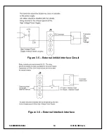
Страница 12: ...he External Inhibit circuit should NOT be used for protection against injury or for safety interlock See External Interlock for this type of safety control EXTERNAL INTERLOCK Interlock connections are provided on the external interface on the rear of the chassis for connection to a safety switch The unit will not operate unless the interlock circuit is closed During high voltage operation opening ...

Страница 13: ...th few exceptions these options and modifications can be retrofitted to your power supply at the factory For price and retrofit arrangements contact the Spellman Sales Department 1 3 Options AOL Adjustable Overload Trip 0 103 OL Overload Trip 103 APT Adjustable Power Trip AT Arc Trip CPC Constant Power Control SS X Non Standard Slow Start X seconds NSS No Slow Start IO Instant ON 200 200Vac 10 thr...

Страница 14: ... After the series name is 1 the maximum voltage in kV 2 the polarity of the unit positive P or negative N 3 the maximum output in watts 4 the option codes for all options that are included Custom units have an X number after the option codes SLS 260 P 2000 AT X Series Name Maximum Voltage Polarity Maximum Power Custom X Number Option ...

Страница 15: ...gh voltage output stack is an air insulated high voltage multiplier assembly with ground at the bottom of the mounting plate assembly and the high voltage output at the top of the corona dome assembly The high voltage output stack is typically vertically mounted and must be mechanically secured via the grounded mounting plate Customers must make the appropriate high voltage connection to the stack...

Страница 16: ...SLS SERIES MANUAL 6 118132 001 RevA Figure 2 1 SLS Series Typical Dimensions SLS180P2000 shown ...

Страница 17: ...y ground No specific phase orientation is required D Electrically mechanically attach the high voltage stack assembly corona dome to the load as seen fit for the application on hand E OPTIONS NOTE See Section 5 for hook up and operating instructions for the options on your unit Custom models may also require set up changes F For initial turn on rotate the KILOVOLT control fully counter clockwise t...

Страница 18: ...and HIGH VOLTAGE ON isolated relay contacts should be used For status and control signals such as HIGH VOLTAGE ON HIGH VOLTAGE OFF and EXTERNAL INHIBIT etc opto isolation should be used If possible analog programming and monitoring signals should be isolated via analog isolation amplifiers Spellman application engineers are available to assist in answering any questions All interface cables should...

Страница 19: ...d the unit will revert to the HIGH VOLTAGE OFF mode Subsequent closing of the interlock circuit will NOT return the unit to the HIGH VOLTAGE ON mode This must be accomplished by depressing the HIGH VOLTAGE ON switch See Figure 3 6 on page 15 for the recommended interface circuits ARC DETECT ARC QUENCH ARC COUNT The ARC INTERVENTION circuit senses dynamic arcing or discharge conditions present at t...

Страница 20: ...132 001 RevA Table 3 1 System Cables Item Description W1 Inverter Output Cable W2 Feedback Cable W3 Ground Cable 4 Load Return Cable customer provided 5 System Ground Cable customer provided Figure 3 1 Typical Operating Setup ...

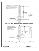
Страница 21: ...ram Out Front Panel Program Voltage 12 EFR Common Optional External Fault Relay 13 EFR Normally Open Optional External Fault Relay 14 Local HV Off Out 15V at Open 25mA at Closed Connect to HV OFF For FP Operation 15 HV OFF 15V at Open 25mA at Closed Connect to Local HV Off Out For FP Operation 16 Remote HV ON 15V 10mA Max HV ON 17 Remote HV OFF Indicator 0 HV ON 15V 10mA Max HV OFF 18 Remote HV ON...

Страница 22: ...SLS SERIES MANUAL 12 118132 001 RevA Figure 3 2B Wiring Diagram for Remote Programming via External Potentiometers Figure 3 2A Wiring Diagram for Remote Programming via Voltage ...

Страница 23: ...enable HIGH VOLTAGE Momentary closure of S2 will enable HIGH VOLTAGE ON Opening S1 will disable HIGH VOLTAGE ON and switch the unit to the HIGH VOLTAGE OFF mode It is recommended to use relay contacts for S1 and S2 Relays should be located as close as possible to the high voltage power supply Coils should be driven from isolated sources Signals are at 15Vdc 25mA max and are only to be used for con...

Страница 24: ...SLS SERIES MANUAL 14 118132 001 RevA Figure 3 5 External Inhibit Interface Circuit Figure 3 6 External Interlock Interface ...

Страница 25: ...SLS SERIES MANUAL 15 118132 001 RevA Figure 3 7 Remote High Voltage On and Remote High Voltage off Indicator ...

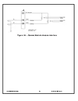
Страница 26: ...SLS SERIES MANUAL 16 118132 001 RevA Figure 3 8 Remote Mode Indicators Interface ...

Страница 27: ...ss can be gained 4 1 Chassis The SLS Series is a compact high efficiency high voltage power supply The unit can supply up to 2000 watts of DC power Output voltages from 160kV to 360kV can be generated The energy levels used and generated by the power supply can be lethal Do not attempt to operate the power supply unless the user has a sufficient knowledge of the dangers and hazards of working with...

Страница 28: ...on and overcurrent conditions in the inverter 4 4 High Voltage Transformer The output of the Inverter is connected to the primary of the step up High Voltage Transformer The High Voltage Transformer is located in the stack assembly beneath the upper grounded baseplate The inverter output is typically an AC high frequency signal about 300 volts in magnitude Due to the high frequency high current fl...

Страница 29: ...a voltage to frequency and a voltage to pulse width converter U17 generates all frequency and pulse width control signals U16 provides specific control functions for the resonant control Power supply inhibit circuits are provided by U22 and relay K3 System Fault control and indication is provided by U19 U20 and U21 and associated circuitry Diagnostic signals are latched and then sent to the FRONT ...

Страница 30: ...ion causes the output voltage of the power supply to rise typically within 50 mS to the rated voltage upon depressing the red HIGH VOLTAGE ON switch 5 4 Non Standard Slow Start SS x The non standard slow start option allows the gradual rise time of the output voltage to be different from the standard of six seconds To order the option place the time desired in seconds after the suffix letter i e S...

Страница 31: ...ny of these faults occur a relay will be activated to provide a remote indication that the power supply has reverted to the Power Down mode The common and normally open contacts are provided Relay contacts are rated at 1A at 30Vdc or 0 5A at 48Vac Connections on the rear panel interface 25 pin D connecter can be made as follows J3 12 Relay Common J3 13 Normally Open Resetting the front panel latch...

Страница 32: ...e test procedures are described in Bulletin STP 783 Standard Test Procedures for High Voltage Power Supplies Copies can be obtained from the Spellman website Test equipment including an oscilloscope a high impedance voltmeter and a high voltage divider such as the Spellman HVD 200 or HVD 400 is needed for performance tests All test components must be rated for operating voltage 6 3 High Voltage Di...

Страница 33: ...ease provide the complete model number and serial number of the power supply in question 7 2 Correspondence and Ordering Spare Parts Each power supply has an identification label on the rear of the chassis that bears its model and serial number When requesting engineering or applications information please state the model and serial number of the power supply If specific components or circuit sect...

Страница 34: ...e returned to the customer The Customer shall pay for shipping to and from Spellman A preliminary estimate for repairs will be given by phone by Customer Service A purchase order for this amount is requested upon issuance of the RMA Number A more detailed estimate will be made when the power supply is received at the Spellman Repair Center In the event that repair work is extensive Spellman will c...

Страница 35: ...ged breach of this warranty No modification amendment supplement addition or other variation of this warranty will be binding unless it is set forth in a written instrument signed by an authorized officer of Spellman Factory Service Procedures For an authorization to ship contact Spellman s Customer Service Department Please state the model and serial numbers which are on the plate on the rear pan...

Отзывы: