SLS SERIES MANUAL
5
118132-001 RevA
Chapter 2
I
NSPECTION
&
I
NSTALLATION
nitial inspection and preliminary checkout procedures
are recommended. For safe operation, please follow
the step-by-step procedures described in Chapter 3,
Operating Systems.
2.1 Initial Inspection
Inspect the package exterior for evidence of damage due
to handling in transit. Notify the carrier and Spellman
immediately if damage is evident. Do not destroy or
remove any of the packing material used in a damaged
shipment.
After unpacking, inspect the assemblies for visible
damage.
Standard Spellman SLS Series high voltage power
supplies and components are covered by warranty.
Custom and special order models (with an X suffix and
the model number) are also covered by warranty.
2.2 Mechanical Installation
Units in the SLS Series are typically comprised to two
parts: the inverter rack and the high voltage output stack.
Inverter Rack:
The inverter rack has front panel holes for standard EIA
rack mounting, it is recommended to support the chassis
by guides or slides. Slides are available for ease of
servicing (SL option).
High Voltage Output Stack:
The high voltage output stack is an air insulated high
voltage multiplier assembly with ground at the bottom of
the mounting plate assembly and the high voltage output
at the top of the corona dome assembly. The high voltage
output stack is typically vertically mounted and must be
mechanically secured via the grounded mounting plate.
Customers must make the appropriate high voltage
connection to the stack via mechanical/electrical means at
the uppermost corona dome assembly.
Danger – Electrocution Hazard!
The top corona dome assembly is at high voltage. It is the
responsibility of the user to:
a)
Make appropriate electrical connection to the
corona dome assembly.
b)
Assure the corona dome assembly is adequate to
suppress corona in their particular usage and
application, additional customer provided corona
relief might be required.
c)
Assure adequate air insulation spacings are used
in the setup and mounting of the stack assembly
(minimum of 1 inch for each 10kV of high
voltage).
d)
Make certain the entire high voltage stack
assembly in contained in a grounded, protective
Faraday Cage
with an interlocked access door.
SLS units generate lethal voltages; they require
appropriate high voltage safety knowledge to safely setup
and use. If you are not properly trained and qualified:
STOP! DO NOT PROCEED! DO NOT USE THIS
EQUIPMENT!
I
Содержание SLS SERIES
Страница 16: ...SLS SERIES MANUAL 6 118132 001 RevA Figure 2 1 SLS Series Typical Dimensions SLS180P2000 shown ...
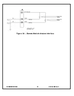
Страница 25: ...SLS SERIES MANUAL 15 118132 001 RevA Figure 3 7 Remote High Voltage On and Remote High Voltage off Indicator ...
Страница 26: ...SLS SERIES MANUAL 16 118132 001 RevA Figure 3 8 Remote Mode Indicators Interface ...


