LPX-200
Industrial Imaging System
6-6
Chapter 6: LPX-200 Routine Upkeep and Care
Re-Filling the Tubehead
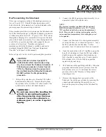
Use this procedure to re-fill the Tubehead in cases where the
gas pressure has dropped below 5 psi @ 70
°
F (refer to Figure
5-1 and 5-2).
1.
Remove the protective cover from the SF6 (sulfur
hexafluoride) cylinder (2). Remove the plug from
the cylinder valve (3) with a 3/8" allen wrench. The
cylinder valve outlet is left-hand threaded.
! WARNING !
Use extreme care while handling the
cylinder to preventing dropping it
after the protective cover has been
removed. Secure the cylinder to a
stationary post, or secure it against
tipping.
2.
Connect the SF6 charging regulator assembly (6), or
equivalent, to the SF6 cylinder valve.
NOTE:
The pressure regulator supplied with the optional
LORAD recharge kit is factory set to 70 - 75 psi @
70F, and locked with a hex nut on the adjustment
knob. However, due to spring tension aging, and/or
various ambient temperatures, this setting may need
to be updated.
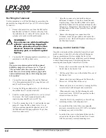
3.
Connect the vacuum pump (10) and the Tubehead
(1) to the regulator assembly (6), using the hoses (8)
and (9) as shown in Figure 6-1.
4.
Leaving the SF6 gas cylinder valve (3) closed, open
the vacuum line (7) counter-clockwise.
5.
Start the vacuum pump and allow it to run for at least
20 minutes. The final vacuum indicated on the
regulator gauge should be at least 25" Hg.
6.
Close the vacuum line valve (7) and turn the vacuum
pump off. Open the SF6 cylinder valve (3) to its
fully open position (against its physical stop). Fill
the Tubehead until the gauge indicates 25 psi, then
close the cylinder valve.
7.
Open the vacuum valve and run the pump an
additional 10 minutes. Close the vacuum line and
stop the pump. Open the SF6 cylinder valve again
and fill the Tubehead to the pressure indicated on the
“
Pressure vs. Temperature
”
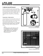
chart (Figure 6-2). When
the Tubehead is at the correct pressure, close the SF6
cylinder valve.
8.
Remove the charging hose connection at the
Tubehead, secure the gas cylinder, and replace the
protective cover. Re-check the pressure and inspect
the Tubehead for leaks.
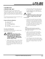
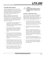
Cleaning - Control Unit Air Filter
Clean the wire mesh air filter within the Control Unit each
month to remove dust, dirt, or debris collected during use.
Large accumulations of dirt can impede the flow of air
through the control unit chassis, which may result in damage
to circuit board components The following describes
removing and cleaning the Control Unit
’
s air filter.
1.
Remove the 4 screws that secure the filter cover to
the left side of the Control Unit.
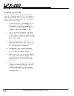
2.
Pull the entire filter cover, with attached filter, out of
the Control Unit.
3.
Remove the 4 hex nuts that secure the filter to the
filter cover. Lift the filter off the cover.
4.
Remove any dirt, dust, or debris by washing the filter
in a solution of mild detergent and warm water.
5.
When complete, rinse the filter thoroughly with
clean, warm water. DO NOT use gasoline or other
solvents to clean the filter.
6.
Allow the filter to dry completely, or blow off any
remaining moisture with compressed air.
7.
Re-install the filter to the filter cover using the
previously removed hex nuts. DO NOT over tighten
or damage may occur to the filter.
8.
Insert the filter cover, with attached filter, into the
cut-out in the left side of the Control Unit. Secure
with the previously removed mounting scres.
Содержание LORAD LPX-200
Страница 1: ...LPX200 ...
Страница 4: ...ii Table of Contents LPX 200 Industrial Imaging System This Page Is Intentionally Blank ...
Страница 47: ......
Страница 49: ......
Страница 50: ......
Страница 51: ......
Страница 52: ......
Страница 53: ......
Страница 54: ......
Страница 55: ......
Страница 56: ......

