LPX-200
Industrial Imaging System
3-2
Chapter 3: Installing the LPX-200 X-ray System
SYSTEM SET UP PROCEDURES
The procedures below describe the set up procedures for both
LPX-200 configurations; liquid-cooled units, and air-cooled
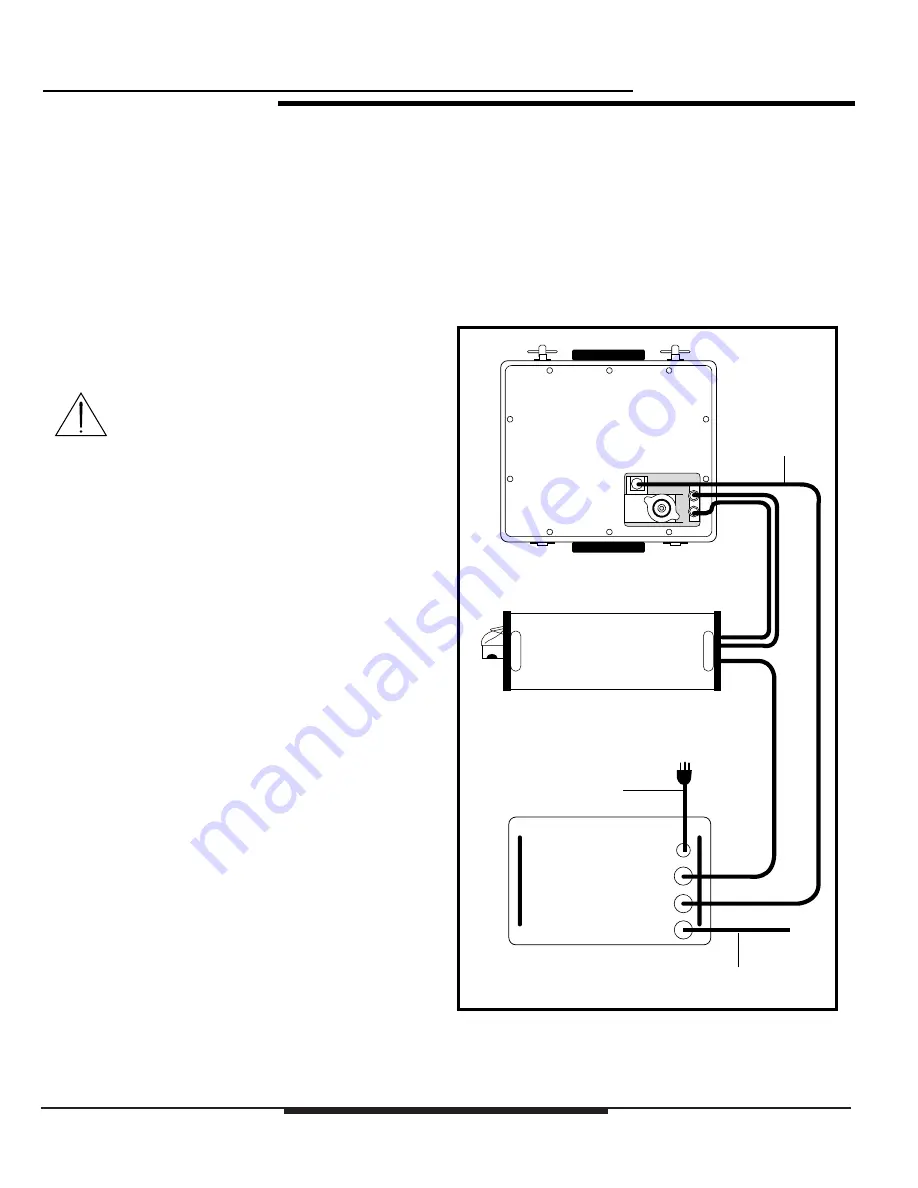
units. Use Figure 3-1 (liquid-cooled), or Figure 3-2 (air-
cooled) as a reference while making the necessary system
connections.
System Interconnections - Liquid Cooled
The following details the connections for setting up a liquid
cooled LPX-200 X-ray System.
! WARNING !
All cables MUST be connected to their
appropriate connectors on the
Control Unit, Cooling Unit, and
Tubehead before applying power to
the system.
1.
Connect the twin hose assembly between the
Tubehead and the Cooling Unit:
◆
Attach the two angled couplings to the fittings on the
back of the Tubehead.
◆
Attached the couplings on the opposite end to the
female fittings on the Cooling Unit.
NOTE:
There is no designated left or right side to the twin
hose assembly. If each coupling is properly seated,
coolant flow through the Tubehead will be achieved.
2.
Install the Cooling Unit power cable:
◆
Connect the male end of the power cable to the
connector labeled
“
Cooler
”
on the Control Unit.
◆
Connect the female end of the power cable to the
connector on the Cooling Unit.
3.
Install the Tubehead Control cable:
◆
Connect the male end of the Control cable to the
connector labeled
“
Tubehead
”
on the Control Unit.
◆
Connect the female end of the Control cable to the
connector on the Tubehead base plate.
4.
Install the line power cable:
◆
Connect the female end of the line power cable to the
connector labeled
“
Power
”
on the Control Unit.
◆
Connect the
“
plug
”
end of the line power cable to the
AC voltage source (see Connecting to Power
instructions later in this section).
5.
Make the External Interlock connection:
◆
If available, connect the Interlock cable to the
connector labeled
“
Interlock
”
on the Control Unit
(see External Interlock instructions later in this
section).
◆
Connect the
“
jumper
”
(supplied) to the connector
labeled
“
Interlock
”
on the Control Unit for units that
do not employ an external interlock system.
Figure 3-1:
LPX-200 Set Up (Liquid Cooled)
Cable
8 pin connector
Cable
10 pin connector
Line Power Cable
to AC Source
CONTROL
UNIT
TUBEHEAD
Twin Hose
COOLER
UNIT
Interlock Connection
or Jumper
Содержание LORAD LPX-200
Страница 1: ...LPX200 ...
Страница 4: ...ii Table of Contents LPX 200 Industrial Imaging System This Page Is Intentionally Blank ...
Страница 47: ......
Страница 49: ......
Страница 50: ......
Страница 51: ......
Страница 52: ......
Страница 53: ......
Страница 54: ......
Страница 55: ......
Страница 56: ......


