background image

7

4. With the transmitter off, place the transmitter steering wheel, throttle trigger and 

auxiliary channels in their desired fail-safe positions (normally brake and straight  

ahead steering).

5. Press and hold the bind button on the transmitter while turning on  

the transmitter.

6. Release the bind button after the green LED flashes

After several seconds the LED on the receiver and the LED on the transmitter will quit 

flashing and remain solid, indicating that the binding process was successful. Once binding 

is complete, the system will automatically connect.

Antenna

At 8.5 inches in length, the receiver antenna is significantly shorter than conventional 

antennas. The receiver has provisions that allow the antenna to exit the top of the receiver 

or at the end of the receiver. To switch antenna positions it is necessary to open the case 

to change the antenna exit position. Like all antennas, it’s important to mount the antenna 

vertically. In most cases the antenna can be mounted inside the body with no loss of range. 

Mount the receiver antenna as recommended by the manufacturer of the vehicle, however, it 

may be necessary to trim the plastic antenna tube (included with your vehicle) to allow the 

antenna to extend at least 1/2” past the tip of the tube.

Note

: If desired, the antenna can be shortened (cut) to exactly 3.6” with negligible loss of 

range, and in some applications the short 3.6” length will make installation easier.

Binding 

(continued)

LED and
Bind Button

Содержание DX3

Страница 1: ...3 Channel 3 Model Memory DSM Racing System ...

Страница 2: ...g Rate Function Mode 26 Sub Trim Function Mode 27 Servo Reversing Function Mode 28 Accessing the Direct Trim Mode 29 Steering Trim STT 30 Throttle Trim THT 31 Grip Lever B Steering Dual Rate Trim Adjustment STG 32 Grip Lever A Brake Endpoint Adjustment BRG Channel 3 Access Brake Endpoint Adjustment 33 Channel 3 Access Fuel Mixture 34 Channel 3 Transmission Shift Selector for vehicles with forward ...

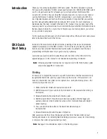
Страница 3: ... the basic programming information necessary to get you racing right away Later when you want to learn more about the specific functions of the DX3 refer to the appropriate page s in this manual for more detailed programming information Note If braking adjustment via Grip Dial A is required refer to the third channel system setup mode page 33 for instructions Binding It s necessary to program the r...

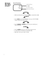
Страница 4: ...CREASE CLEAR DIRECT 3 Press the INCREASE or DECREASE key to move the cursor to the desired servo direction REV NORM CHANNEL ENTER SYSTEM 4 Press the CHANNEL key once to access the throttle servo reversing screen 5 To select the direction of the throttle servo repeat Step 3 above 6 Repeat Steps 2 and 3 to adjust channel 3 if needed DX3 Quick Start Setup continued st REV NORM Indicates Current Chann...

Страница 5: ...hrottle trigger to full brake and hold noting that the screen now displays BRM Adjust the brake value by pressing the INCREASE or DECREASE keys to obtain the desired full brake position Channel 3 Adjustment If third channel is not required proceed to Step 8 CHANNEL ENTER SYSTEM 7 Press the CHANNEL key once F3 will appear on the screen MODE CHANNEL ENTER SYSTEM 8 Move the grip dial A in the desired...

Страница 6: ...positions are transferred from the transmitter to the receiver during binding See binding below for more details It is necessary to bind the receiver to the transmitter during the first installation and is recommended when the receiver is moved from one vehicle to another Receivers can be re bound to the same transmitter or to other transmitters an infinite number of times Also multiple receivers ca...

Страница 7: ...er than conventional antennas The receiver has provisions that allow the antenna to exit the top of the receiver or at the end of the receiver To switch antenna positions it is necessary to open the case to change the antenna exit position Like all antennas it s important to mount the antenna vertically In most cases the antenna can be mounted inside the body with no loss of range Mount the receiv...

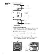
Страница 8: ...tion to be adjusted The throttle trim value screen will appear automatically Channel 3 Servo Trim Adjustment If Activated 3 With the transmitter power switch on move the digital Grip Lever A in the desired position to be adjusted The channel 3 value screen will appear automatically Direct Trim Access STT 0 THT 0 FN3 0 Steering Trim Throttle Trim Decrease Grip Lever A Channel 3 Increase Indicates S...

Страница 9: ...trim levers for throttle and steering Two assignable electronic grip levers Third channel accessible through Grip Dial A Direct display trim function Sub trim Steering dual rate Independent steering endpoint adjustments Brake throttle endpoint adjustment Low battery alarm Charge jack receptacle rechargeable batteries not included order JRPB958 System Features ...

Страница 10: ...ress down where it says press and push the cover in the direction of the arrow Remove the battery case and install 8 AA batteries in the direction as molded into the battery case If transmitter voltage fails to register check for correct battery installation and voltage ...

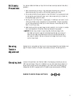
Страница 11: ... Also watch carefully for fishing lines that can get tangled in the propeller CAUTION Control of your model is impossible without sufficient voltage for the transmitter and receiver A weak transmitter battery will decrease your range of operation and a weak receiver battery will slow servo movement and decrease your range of operation Check your receiver pack voltage often to avoid losing control of...

Страница 12: ...ollers are set up for B E C operation and plug directly into your receiver See Figure A for a typical setup and check your speed controller s manual for correct installation Figure A Connections to B E C and receiver with mechanical speed controller Ni Cd battery and speed controller are not included in the radio set Figure B Connections to B E C and receiver with electronic speed controller Ni Cd...

Страница 13: ...elected function DECREASE Used to decrease the value of the selected function To enter the System Mode press the MODE andCHANNEL keys simultaneously and hold while turning on the transmitter MODE CHANNEL ENTER SYSTEM INCREASE DECREASE CLEAR DIRECT To enter the Function Mode press the MODE key while the transmitter is on Press the INCREASE and DECREASE keys simultaneously to clear the screen or ret...

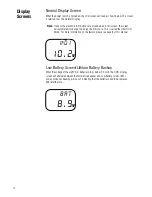
Страница 14: ...play the trim in use This is called the Direct Trim Mode For more information on the feature please see page 8 of this manual Low Battery Screen Lithium Battery Backup When the voltage of the eight AA batteries drops below 9 0 volts the DX3 s display screen will alternate between the Normal see above and Low Battery screen BAT and a continuous beeping will occur indicating that the batteries need ...

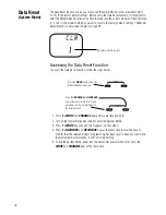
Страница 15: ... it becomes necessary to replace the lithium battery return your system to the Horizon Service Center for repair see address page 38 Memory Backup Screen If the Memory Backup screen appears this indicates the possibility of a memory issue or the lithium battery is dead If you switch the power off and on again and transmitter is in the default mode with all data lost it is suggested that the DX3 tr...

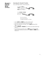
Страница 16: ...unction or channel 3 function as shown here on the System Mode flow chart Information for each function is located on the page number listed next to the function name on the flow chart To exit the System Mode press the MODE and CHANNEL keys at the same time or simply turn off the transmitter Accessing the System Mode MD1 1 clr 1 FN3 ln Model Name Entry Page 17 Date Reset Page 18 Channel 3 Function P...

Страница 17: ...e changed Press the INCREASE or DECREASE keys to select the correct letter number to be used INCREASE DECREASE CLEAR DIRECT 1 Press the MODE and CHANNEL keys at the same time and hold 2 Turn on the transmitter power switch to enter the System Mode 3 MD1 should now be present on the screen 4 Press the INCREASE or DECREASE keys to select the correct letter number for the first character flashing 5 To ...

Страница 18: ...tion MODE CHANNEL ENTER SYSTEM Press the INCREASE or DECREASE keys at the same time to reset clear all settings for the selected model to the factory default INCREASE DECREASE CLEAR DIRECT 1 Press the MODE and CHANNEL keys at the same time and hold 2 Turn on the transmitter power switch to enter the System Mode 3 Press the MODE key once until CLR appears on the screen 4 Press the INCREASE and DECR...

Страница 19: ...19 Page intentionally left blank ...

Страница 20: ...mission gear shift channel This feature is designed for use only with vehicles equipped with this feature As mentioned previously this function is accessible through the Grip Dial A In this function the servo s travel can be selected to only three positions left center and right The left and right travel values are determined by the Travel Adjust Function page 24 The center position can be adjuste...

Страница 21: ...tion servo movement 0 Inhibited Grip Dial A Braking is now activated 1 Press the MODE and CHANNEL keys at the same time and hold 2 Turn on the transmitter power switch to enter the System Mode 3 MD1 should now be present on the screen Press the MODE key twice until FN3 appears on the screen 4 Press the INCREASE or DECREASE keys to select the correct Channel 3 function type to be used 5 To access t...

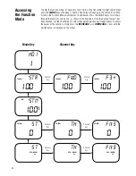
Страница 22: ...in the flow chart Once the desired function has been reached use the channel key to select the appropriate channel if applicable To adjust the values of the function simply press the INCREASE or DECREASE keys until the desired value is displayed on the screen Accessing the Function Mode Mode Key Channel Key md1 1 str 100 fwd 100 f3 100 stm 100 st 0 th 0 fn3 0 st th fn3 TRV ADJ TRV ADJ TRV ADJ SB TR...

Страница 23: ...ess the INCREASE or DECREASE keys to select the desired model to be used 1 2 or 3 INCREASE DECREASE CLEAR DIRECT 1 Turn the transmitter power switch on 2 Press the MODE key to access the Function Mode 3 Press the MODE key until MDL appears on the screen 4 Press the INCREASE or DECREASE keys to select the desired model number 1 2 or 3 5 Press the MODE key to access the Travel Adjust function 6 To e...

Страница 24: ... mechanical linkage adjustment The screens below are accessed by turning the wheel to the desired direction to be adjusted left or right by moving the trigger to the forward or backward brake position or by moving the Grip Lever A to the forward or back positions Channel 3 Screens Optional Travel Adjust Function Mode stl 100 TRV ADJ str 100 TRV ADJ fwd 100 TRV ADJ f3 100 TRV ADJ f3 100 TRV ADJ Ind...

Страница 25: ... steering left Throttle FWD forward or BRM braking or reverse Channel 3 optional F3 or F3 function 3P only 5 Move the steering wheel trigger or Grip Lever A in the desired direction for adjustment left right forward reverse or brake Press the INCREASE or DECREASE key to achieve the desired amount of travel Move the wheel trigger or Grip Lever A in the opposite direction to adjust the travel in the...

Страница 26: ... to maximize the steering rate needed for the particular track conditions Accessing the Steering Rate Function To access the Steering Rate Function follow the steps below Press the MODE key until D R STM appears on the screen MODE CHANNEL ENTER SYSTEM Press the INCREASE or DECREASE keys to achieve the desired steering rate value INCREASE DECREASE CLEAR DIRECT 1 Turn on the transmitter power switch...

Страница 27: ...rim Function To access the Sub Trim function follow the steps below Press the MODE key until SB TRM appears on the screen MODE CHANNEL ENTER SYSTEM Press the CHANNEL key to select the desired channel to be adjusted ST Steering TH Throttle FN3 Channel 3 optional Press the INCREASE or DECREASE keys to achieve the desired sub trim value INCREASE DECREASE CLEAR DIRECT 1 Turn on the transmitter power s...

Страница 28: ...T Steering TH Throttle FN3 Channel 3 optional Press the INCREASE or DECREASE keys to toggle between REV and NORM INCREASE DECREASE CLEAR DIRECT 1 Turn the transmitter power switch on 2 Press the MODE key to access the Function Mode 3 Press the MODE key until REV NORM appears in small letters to the right of the screen 4 Press the CHANNEL key to select the channel to be changed ST Steering TH Throt...

Страница 29: ...ove the trim lever in the desired direction until the correct amount of trim is achieved Once the desired trim is achieved the screen will return to the Normal display screen after approximately five seconds from the last trim input If the MODE or CHANNEL keys are pressed any time during the five seconds the system will return to the previous screen in use Accessing the Direct Trim Mode stt 0 tht 0 ...

Страница 30: ...ide alter the endpoint value To adjust the steering trim servo position move the electronic steering trim lever either to the left or the right As soon as the trim is moved the STT steering trim screen will appear and will continue to be displayed unless the trim lever is untouched for a period of five seconds To reset the trim value to 0 press the INCREASE and DECREASE keys at the same time while ...

Страница 31: ...hrottle trim will override alter the endpoint value To adjust the throttle trim servo position move the electronic steering trim lever either up or down As soon as the trim is moved the THT throttle trim screen will appear and will continue to be displayed unless the trim lever is untouched for a period of five seconds To reset the trim value to zero press the INCREASE and DECREASE keys at the same...

Страница 32: ...e value will not always increase or decrease or beep once for each time the Grip Lever B is moved To adjust the steering dual rate value move the electronic Grip Lever B either left or right As soon as the trim is moved the STG steering dual rate screen will appear and will continue to be displayed unless the Grip Lever B is untouched for a period of five seconds To reset the trim value to the fact...

Страница 33: ...Lever A is moved To adjust the brake endpoint value move the electronic Grip Lever A either left or right As soon as the grip lever is moved the BRG Travel Adjust screen will appear and will continue to be displayed unless the Grip Lever A is untouched for a period of five seconds To reset the brake endpoint value to the factory preset setting of 50 press the INCREASE and DECREASE keys at the same ...

Страница 34: ...e positions left center right and gear 1 2 and 3 When the 3P function is selected there will be no Direct Trim Access screen present as with previous functions Please refer to Diagram A below for proper shifting procedures Note As mentioned previously in this function the travel adjust function is used to set the first and second gear servo travel positions while the sub trim feature is used to adj...

Страница 35: ...35 DX3 Data Sheet ...

Страница 36: ...36 DX3 Data Sheet ...

Страница 37: ...37 DX3 Data Sheet ...

Страница 38: ...peration or installation of this product please feel free to call a product support representative at 1 877 504 0233 If your equipment needs to be repaired ship it to Horizon Service Center ATTN Spektrum Service 4105 Fieldstone Road Champaign IL 61822 Include your complete name and address information inside the carton and clearly write it on the outer label return address area Include a brief sum...

Страница 39: ...39 Notes ...

Страница 40: ... 2005 Horizon Hobby Inc 4105 Fieldstone Road Champaign Illinois 61822 877 504 0233 horizonhobby com SPMM100 6 0 5 4 8 2 0 0 1 0 5 9 7671 ...

Отзывы: