background image

Dongle Cables

Preparing for Installation

25

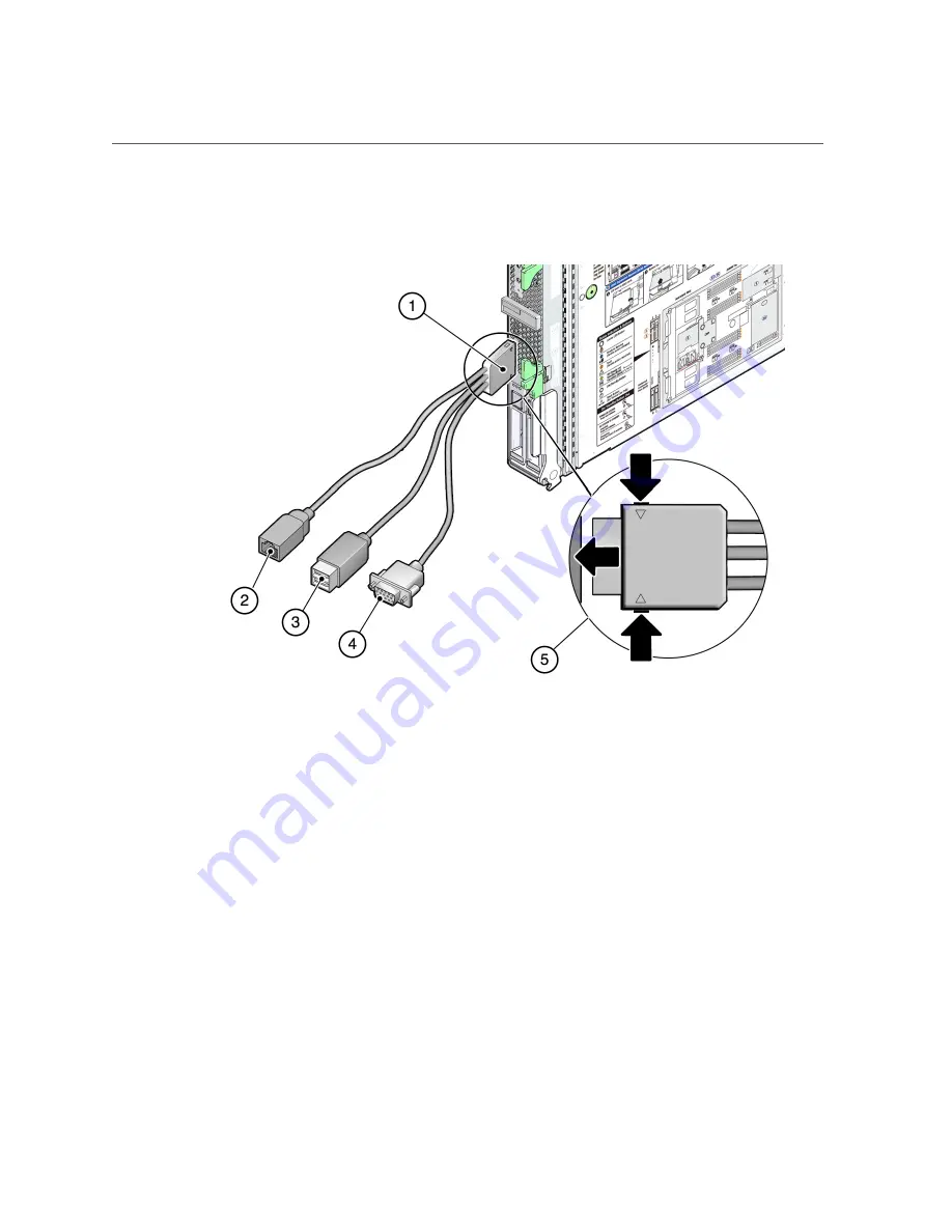
FIGURE   1

UCP-3 Three-Connector Dongle Cable

Figure Legend

1

Dongle connector attaching to the server module UCP

2

RJ-45 serial connector

3

USB 2.0 (two connectors)

4

VGA 15-pin female connector

5

Insertion and release buttons

Содержание E35202-05

Страница 1: ...Part No E35202 05 May 2014 SPARC T5 1B Server Module Installation Guide ...

Страница 2: ......

Страница 3: ...documentation shall be subject to license terms and license restrictions applicable to the programs No other rights are granted to the U S Government This software or hardware is developed for general use in a variety of information management applications It is not developed or intended for use in any inherently dangerous applications including applications that may create a risk of personal inju...

Страница 4: ...tion shall be subject to license terms and license restrictions applicable to the programs No other rights are granted to the U S Government Ce logiciel ou matériel a été développé pour un usage général dans le cadre d applications de gestion des informations Ce logiciel ou matériel n est pas conçu ni n est destiné à être utilisé dans des applications à risque notamment dans des applications pouva...

Страница 5: ...9 Inventory 19 Handling Precautions 20 ESD Precautions 20 Tools Needed for Installation 22 Plan Communication With the Server Module During Installation 22 Dongle Cables 24 Installing the Server Module 29 Prepare the Modular System and Server Module 29 Install Optional Components 30 Insert the Server Module Into the Chassis 31 Powering On the Server Module for the First Time 35 Powering On the Hos...

Страница 6: ... the Host Through the CMM SER MGT Port CLI 41 Installing the OS 43 Configure the Preinstalled OS 44 Oracle Solaris Configuration Parameters 44 Reach a State to Install a Fresh OS Oracle ILOM Web Interface 46 Reach a State to Install a Fresh OS Oracle ILOM CLI 49 Assign a Static IP Address to the SP 50 Glossary 53 Index 59 ...

Страница 7: ...included in the documentation library at http www oracle com goto T5 1B docs Access to Oracle Support Oracle customers have access to electronic support through My Oracle Support For information visit http www oracle com pls topic lookup ctx acc id info or visit http www oracle com pls topic lookup ctx acc id trs if you are hearing impaired Documentation Accessibility For information about Oracle ...

Страница 8: ...8 SPARC T5 1B Server Module Installation Guide May 2014 ...

Страница 9: ... Components on page 12 3 Review the server module requirements Confirming Server Specifications on page 15 4 Confirm that you received all the items you ordered Inventory on page 19 5 Review safety and ESD precautions Handling Precautions on page 20 ESD Precautions on page 20 6 Gather the required tools Tools Needed for Installation on page 22 7 Choose a method for connecting to the server module ...

Страница 10: ...ess to the SP Assign a Static IP Address to the SP on page 50 Related Information Server Module Overview on page 10 Front and Rear Panel Components on page 12 Server Module Overview Feature Description Processor One 16 core 128 thread SPARC T5 processor Architecture SPARC V9 architecture ECC protected Platform group sun4v Platform name SPARC T5 1B Memory 16 slots supporting 8 GB or 16 GB DDR3 DIMM...

Страница 11: ...deo port Midplane I O Four x8 PCIe interfaces two to NEMs two to PCIe EMs operating at Gen2 speeds Two 10 100 1000 GbE interfaces one per NEM One 10 100 Ethernet management port to CMM OS Oracle Solaris OS Note Refer to the Server Module Product Notes for details on software that is preinstalled and for information about required patches for supported Oracle Solaris OS releases Remote management S...

Страница 12: ...le Installation Guide May 2014 Front and Rear Panel Components No Description 1 Locator LED white also functions as the physical presence switch 2 Ready to Remove LED blue 3 Fault LED amber 4 OK LED green 5 Power button 6 Reset button NMI for service use only ...

Страница 13: ...jector arm latch 11 RFID tag provides the serial number of the server module 12 Top cover release button 13 UCP 14 Drive slots 15 Rear chassis power connector 16 Rear chassis data connection Refer to Server Module Service Interpreting LEDs for more information about the LEDs Related Information Server Module Overview on page 10 Installation Task Overview on page 9 ...

Страница 14: ...14 SPARC T5 1B Server Module Installation Guide May 2014 ...

Страница 15: ...pecifications on page 15 Electrical Specifications on page 16 Environmental Specifications on page 16 Related Information Installing the Server Module on page 29 Installation Task Overview on page 9 Server Module Overview on page 10 Physical Specifications Description U S Metric Height 12 9 in 327 mm Width 1 8 in 44 mm Depth 20 1 in 511 mm Weight 17 lb 7 7 kg Minimum service clearance front 36 in ...

Страница 16: ...e First Time on page 35 Environmental Specifications This topic includes these specifications Temperature humidity and elevation Shock and vibration TABLE 1 Temperature Humidity and Elevation Specifications Operating Nonoperating Description U S Metric U S Metric Notes Temperature maximum 41 to 95 F at 0 to 2953 ft 5 to 35 C at 900m 40 to 158 F at 0 to 2953 ft 40 to 70 C at 900m Above 2953 ft 900m...

Страница 17: ... Specifications Confirming Server Specifications 17 Description Operating Notes Vibration vertical 0 15G 5 to 500 HZ swept sine Vibration horizontal 0 10G Related Information Installing the Server Module on page 29 ...

Страница 18: ...18 SPARC T5 1B Server Module Installation Guide May 2014 ...

Страница 19: ...ntory on page 19 Handling Precautions on page 20 ESD Precautions on page 20 Tools Needed for Installation on page 22 Plan Communication With the Server Module During Installation on page 22 Dongle Cables on page 24 Related Information Installing the Server Module on page 29 Installation Task Overview on page 9 Inventory ...

Страница 20: ...dule During Installation on page 22 Dongle Cables on page 24 Handling Precautions Use both hands to carry the server module Extend the ejector arms on the front panel only while they need to be in that position to perform a step in a task Related Information Physical Specifications on page 15 Inventory on page 19 ESD Precautions on page 20 Tools Needed for Installation on page 22 Plan Communicatio...

Страница 21: ...r an antistatic grounding strap connected to a metal surface on the chassis when you work on server components The following figure shows the modular system chassis ground connector for which you can connect antistatic equipment Related Information Inventory on page 19 Handling Precautions on page 20 Tools Needed for Installation on page 22 Plan Communication With the Server Module During Installa...

Страница 22: ...ESD Precautions on page 20 Plan Communication With the Server Module During Installation on page 22 Inventory on page 19 Plan Communication With the Server Module During Installation There are several methods to communicate with the server module during the initial installation Plan which method you will use Before you perform the installation arrange to have the equipment information and permissi...

Страница 23: ...ed on the type of Oracle ILOM interface you want to use Web Interface Power On the Host Through the CMM SER MGT Port CLI on page 41 CLI Power On the Host Through the CMM CLI on page 37 2 Serial From Server module SP UCP port To Terminal device A terminal device and serial cable Dongle cable You communicate directly with Oracle ILOM on the server module SP using the CLI See Power On the Host Throug...

Страница 24: ...ule Caution Dongle cables should be removed when not in use These cables have not been evaluated for electromagnetic compatibility compliance and are not to be used during normal system operation There are two types of dongle cables you can use UCP 3 Three connector dongle cable preferred ships with the server module Use the RJ 45 connector to connect to the server module SP UCP 4 Four connector d...

Страница 25: ...llation 25 FIGURE 1 UCP 3 Three Connector Dongle Cable Figure Legend 1 Dongle connector attaching to the server module UCP 2 RJ 45 serial connector 3 USB 2 0 two connectors 4 VGA 15 pin female connector 5 Insertion and release buttons ...

Страница 26: ...ing to the server module UCP 2 RJ 45 serial connector Do not use this connector on the UCP 4 3 DB 9 serial male connector TTYA 4 USB 2 0 two connectors 5 VGA 15 pin female connector 6 Insertion and release buttons Related Information Inventory on page 19 Handling Precautions on page 20 ESD Precautions on page 20 Tools Needed for Installation on page 22 ...

Страница 27: ...Dongle Cables Preparing for Installation 27 Plan Communication With the Server Module During Installation on page 22 ...

Страница 28: ...28 SPARC T5 1B Server Module Installation Guide May 2014 ...

Страница 29: ...e First Time on page 35 Installation Task Overview on page 9 Prepare the Modular System and Server Module You must install and configure the Sun Blade 6000 modular system chassis before installing the server module 1 Ensure that the modular system is installed and functional Satisfying the following conditions ensures a straightforward installation of the server module a Install the modular system...

Страница 30: ...the server module s initial configuration are installed in the server module before it is shipped These optional components are identified on the customer information sheet included with the server module s packaging However if you ordered optional components separately you must install them in the server module before you install the server module in the modular system chassis 1 Install any optio...

Страница 31: ...physical installation As soon as you insert the server module in a powered modular system power is supplied to the server module and the SP generates messages If you want to see these messages be ready to connect using one of the methods in Plan Communication With the Server Module During Installation on page 22 5 Locate the slot in the chassis where you plan to install the server module A filler ...

Страница 32: ...server module into the chassis and close the ejector levers panels 2 and 3 11 Monitor status messages when power is applied to the server module panel 4 When the server module is plugged in standby power is supplied to the SP After about 10 seconds the front panel LEDs blink three times then the green OK LED blinks for a few minutes The server module SP generates messages as soon as the server mod...

Страница 33: ...er Module Into the Chassis Installing the Server Module 33 Related Information Prepare the Modular System and Server Module on page 29 Install Optional Components on page 30 Front and Rear Panel Components on page 12 ...

Страница 34: ...34 SPARC T5 1B Server Module Installation Guide May 2014 ...

Страница 35: ...ated Information Installation Task Overview on page 9 Servers Administration Powering On the Host for the First Time Based on the connection method you selected from Plan Communication With the Server Module During Installation on page 22 perform the tasks in the applicable row of this table Description Links Method 1 web interface Through a browser that is on the same network as the CMM power on ...

Страница 36: ...ion supports both the Oracle ILOM CLI and the web interface this procedure uses the web interface This procedure assumes that the CMM Oracle ILOM is running version 3 1 or higher Note By default the server module is configured to use DHCP to obtain the IP address for the SP 1 Ascertain the IP addresses for the CMM 2 Ensure that the CMM is connected to the network you are on The network connection ...

Страница 37: ...stalled OS 9 In the left navigation panel click on Remote Control Redirection 10 Select Use serial redirection and click Launch Remote Console As the host boots messages are displayed in the serial console You are automatically prompted for Oracle Solaris OS configuration information 11 Configure the Oracle Solaris OS to meet your needs See Installing the OS on page 43 Related Information Plan Com...

Страница 38: ...racle TM Integrated Lights Out Manager Version 3 x x Warning password is set to factory default You are now logged into the Oracle ILOM CMM CLI Note When you are ready to log out of the Oracle ILOM CMM type exit 5 If you do not plan to use the preinstalled OS do not perform the remaining steps Instead go to Reach a State to Install a Fresh OS Oracle ILOM CLI on page 49 6 Navigate to the server mod...

Страница 39: ...rn to Oracle ILOM type Hash Dot To see information about available Oracle ILOM commands type help To return to the initialization type start HOST console 9 The server module hardware installation is now complete You can now configure the Oracle Solaris OS to meet your needs See Installing the OS on page 43 Related Information Plan Communication With the Server Module During Installation on page 22...

Страница 40: ...terminal or terminal emulator 4 Type the user name and password when prompted The default user is root The default password is changeme You are now logged into Oracle ILOM on the server module SP 5 If you do not plan to use the preinstalled OS do not perform the remaining steps Instead go to Reach a State to Install a Fresh OS Oracle ILOM CLI on page 49 6 Power on the host start System Are you sur...

Страница 41: ...MGT Port CLI You can access the server module SP by first accessing Oracle ILOM CMM through a terminal or terminal emulator connected to the RJ 45 serial port on the chassis Then you can connect to the server module SP through the Oracle ILOM CMM CLI 1 Verify that the terminal laptop or terminal server that will connect to the chassis is operational 2 Configure the terminal device or terminal emul...

Страница 42: ...s The MAC address for each CMM and SP is unique 5 Log into Oracle ILOM on the CMM by typing your user name and password The factory default Oracle ILOM root password is changeme but might have been changed in your environment You are now logged into the Oracle ILOM CMM web interface After you have successfully logged in the Oracle ILOM CMM displays its default command prompt 6 Navigate to the serv...

Страница 43: ...the server module host 9 The server module hardware installation is now complete You can now configure the Oracle Solaris OS to meet your needs See Installing the OS on page 43 Related Information Plan Communication With the Server Module During Installation on page 22 Installing the OS Perform the set of tasks that apply to your situation Description Links Configure the preinstalled OS Configure ...

Страница 44: ...module You need to collect only the information that applies to your installation environment Note The configuration parameters vary slightly based on the release of the Oracle OS you are installing Information for Installation Description or Example Your Values Denotes the default value Language Select from the list of available languages for the OS English Locale Select your geographic region fr...

Страница 45: ...ystem resides DNS or NIS NIS and NIS If you chose NIS or NIS do you want to specify a name server or let the installation program find one Specify One Find One If you choose NIS Specify a NIS domain Indicate whether to specify a NIS server or search for one DNS If you chose DNS provide IP addresses for the DNS server You must enter at least one IP address but you can enter up to three addresses Yo...

Страница 46: ...ses itself by using the ICMP for router discovery If you are using the CLI the software detects an IP address when the system is booted You can select None if you do not have a router or do not want the software to detect an IP address at this time The software automatically tries to detect an IP address on reboot Specify one Detect One None Time zone How do you want to specify your default time z...

Страница 47: ...assword c In the upper left corner change Manage Chassis to Manage Blade_n where n is the slot in which the server module is installed Note These tasks are described in Power On the Host Through the CMM Web Interface on page 36 3 In the Oracle ILOM web interface in the left navigation pane select Host Management Host Boot Mode The Host Boot Mode page is displayed 4 Apply these changes to the Host ...

Страница 48: ...http www oracle com goto Solaris11 docs Oracle Solaris 10 Installation Guide Planning for Installation and Upgrade choosing an Oracle Solaris installation method at http www oracle com goto Solaris10 docs For a list of valid boot commands type 0 ok help File boot specifier boot kernel default or other file Examples boot boot kernel from default device Factory default is to boot from DISK if presen...

Страница 49: ...g an Oracle Solaris installation method at http www oracle com goto Solaris10 docs 2 From Oracle ILOM set the OBP auto boot parameter to false set HOST bootmode script setenv auto boot false This setting prevents the server module from booting from the preinstalled OS When you use bootmode the change applies only to a single boot and expires in 10 minutes if the power on the host is not reset 3 Wh...

Страница 50: ...om tape boot disk myunix as boot myunix from disk with flags as dload filename addr debug load of file over network at address Examples 4000 dload export root foo test go if executable program execute it or if Forth program compile it Related Information Configure the Preinstalled OS on page 44 Reach a State to Install a Fresh OS Oracle ILOM Web Interface on page 46 Assign a Static IP Address to t...

Страница 51: ...nvironment subnet might require a different netmask Use a netmask number most appropriate to your environment 5 Verify that the pending parameters are set correctly show SP network SP network Targets Properties commitpending Cannot show property dhcp_server_ip xxx xxx xxx xxx ipaddress xxx xxx xxx xxx ipdiscovery dhcp ipgateway xxx xxx xxx xxx ipnetmask 255 255 255 0 macaddress 00 21 28 C1 6E C5 m...

Страница 52: ...pe the show SP network command again to verify that the parameters have been updated 7 Set the static IP address when you configure the Oracle Solaris OS See Configure the Preinstalled OS on page 44 Related Information Configure the Preinstalled OS on page 44 Oracle Solaris Configuration Parameters on page 44 ...

Страница 53: ...le BMC Baseboard management controller BOB Memory buffer on board C chassis For servers refers to the server enclosure For server modules refers to the modular system enclosure CMA Cable management assembly CMM Chassis monitoring module server modules only The CMM is the service processor in the modular system that contains server modules Oracle ILOM runs on the CMM providing lights out management...

Страница 54: ...tain NEMs See NEM FRU Field replaceable unit H HBA Host bus adapter host The part of the server or server module with the CPU and other hardware that runs the Oracle Solaris OS and other applications The term host is used to distinguish the primary computer from the SP See SP hot pluggable Describes a component that can be replaced with power applied but the component must be prepared for removal ...

Страница 55: ...nly The modular system provides Oracle ILOM through its CMM MSGID Message identifier N name space Top level Oracle ILOM target NEBS Network Equipment Building System Netra products only NEM Network express module server modules only NEMs provide Ethernet and SAS connectivity to storage modules NET MGT Network management port An Ethernet port on the server SP the server module SP and the CMM NIC Ne...

Страница 56: ...r I O features such as Gigabit Ethernet and Fibre Channel POST Power on self test PROM Programmable read only memory PSH Predictive self healing R REM RAID expansion module server modules only Sometimes referred to as an HBA See HBA Supports the creation of RAID volumes on drives S SAS Serial attached SCSI SCC System configuration chip SER MGT Serial management port A serial port on the server SP ...

Страница 57: ...Telecommunications Industry Association Netra products only Tma Maximum ambient temperature U U S NEC United States National Electrical Code UCP Universal connector port UI User interface UL Underwriters Laboratory Inc UTC Coordinated Universal Time UUID Universal unique identifier W WWN World wide name A unique number that identifies a SAS target ...

Страница 58: ...58 SPARC T5 1B Server Module Installation Guide May 2014 ...

Страница 59: ...ecting to the server CMM NET MGT port CLI 37 CMM NET MGT port web interface 36 CMM SER MGT port CLI 41 UCP connector 39 connection methods 22 connector covers 31 cooling 10 customer information sheet 19 D data connector Installation 12 depth 15 DHCP server displaying IP address 50 dimensions 15 DIMMs types 10 dongle cables 22 24 39 E ejector arms 31 electrical specifications 16 elevation specifica...

Страница 60: ...nstallation 15 19 Power button 12 power calculator 16 power connector 12 powering on the server module 35 precautions ESD 20 handling 20 processor architecture 10 R rear panel components 12 remote console 36 Reset button 12 root password default 36 S serial cable pin assignments 41 serial port connection 22 24 serial redirection 36 server module configuring the OS 44 features 10 inserting into cha...

Страница 61: ... overview installation 9 temperature specifications 16 tools for installation 22 U UCP cables 24 UCP connector 10 12 39 understanding the server module 9 USB connection 24 V VGA connection 24 vibration specifications 16 W web interface 36 weight 15 width 15 ...

Страница 62: ...62 SPARC T5 1B Server Module Installation Guide May 2014 ...

Отзывы: