


6
GB
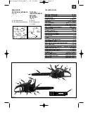
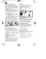
GENERAL INFORMATION (FIG. 2C)
1. Chain
bar
2. Saw
chain
3. Chain tensioning screw
4. Spark mesh(inside exhaust)
5. Chain brake lever / front hand
guard
6. Front
handle
7. Starter
handle
8. Spark
plug
9. Air filter cover
10. Stop switch
11. Safety lock
12. Oil tank cap
13. Fan housing
14. Fuel tank cap
15. Rear handle / bootstrap
16. Operating switch
17. Choke / (carburetor setting)
18. Bar fastening nut
19. Throttle lever
20. Chain catch
21. Exhaust cover
22. Stop claw
23. Chain guard
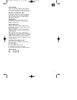
ACCESSOIRIES
1
bottle 2-stroke oil
1
bottle chain oil
1
sparking plug spanner
1
fuel mixing bottle
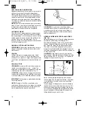
SAFETY FEATURES
Numbers preceding the descriptions correspond with
the numbers on preceding page to help you locate
the safety feature.
2
LOW KICKBACK SAW CHAIN
helps
significantly reduce kickback, or the intensity of
kickback, due to specially designed depth
gauges and guard links.
5
CHAIN BRAKE LEVER / HAND GUARD
protects the operatorʼs left hand in the event it
slips off the front handle while saw is running.
5 CHAIN
BRAKE
is a safety feature designed to
reduce the possibility of injury due to kickback by
stopping a moving saw chain in milliseconds. It is
activated by the CHAIN BRAKE lever.
10 STOP SWITCH
immediately stops the engine
when tripped. Stop switch must be pushed to ON
position to start or restart engine.
11 SAFETY TRIGGER
prevents accidental
acceleration of the engine. Throttle trigger (19)
cannot be squeezed unless the safety latch is
depressed.
20 CHAIN CATCHER
reduces the danger of injury
in the event saw chain breaks or derails during
operation. The chain catcher is designed to
intercept a whipping chain.
NOTE:
Study your saw and be familiar with its parts.
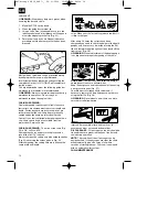
ASSEMBLY INSTRUCTIONS
TOOLS FOR ASSEMBLY
You will need these tools to assemble your chain
saw:
1. Ring wrench SW 11
2.
Screwdriver / spark plug wrench
Assembly Requirements
WARNING
: DO NOT start saw engine until unit is
properly prepared.
Your new chain saw will require adjustment of chain,
filling the fuel tank with correct fuel mixture and filling
the oil tank with lubricating oil before the unit is ready
for operation.
Read the entire user manual before attempting to
operate your unit. Pay particular attention to all safety
precautions.
This manual contains not only safety information but
also general information on how to assemble,
operate and service the saw.
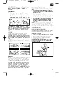
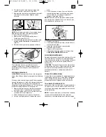
GUIDE BAR / SAW CHAIN / CLUTCH COVER
INSTALLATION
WARNING
: Always wear protective gloves when
handling chain.
TO INSTALL GUIDE BAR:
To ensure the bar and chain receive oil, ONLY USE
THE ORIGINAL STYLE BAR with the oil passage
hole (A) as illustrated above (Fig. 3A).
1.
Make sure the Chain brake lever is pulled back
into the DISENGAGED position (Fig. 3B)
2.
Remove the bar fastening nut (B). Remove the 2
screws of the chain brake cover (C). Remove the
chain brake cover
by pulling it straight out with a
strong tug (Fig. 3C).
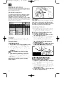
Note:
The chain may sag a little. This is normal.
3.
Using a screwdriver, run the adjustment screw
(D) COUNTERCLOCKWISE until the TANG (E)
(projecting prong) is to the end of its travel
toward the clutch drum and sprocket (Fig. 3D).
4.
Place the slotted end of the guide bar over the
bar bolts (F). Position the bar so that the
adjustment TANG fits into the lower hole (G) on
the guide bar (Fig. 3E).
Anleitung SCS 38_SPK7:_ 20.11.2006 15:43 Uhr Seite 6


