-38-
For Machines Mfd. Since 12/21
South Bend Tools
Model SB1102
S E R V I C E
Replace the V-belts if you notice fraying,
cracking, glazing, or any other damage. A worn/
damaged V-belt will not provide optimum power
transmission from the motor to the drums.
V-belt removal and replacement is simply a
matter of raising the motor and loosening the
V-belts until you can roll them off the pulleys,
replacing them with a MATCHED set, then re-
tensioning them. Always replace both belts at the
same time with a new matched set.
Note:
A matched set means both the V-belts are
the same size and also have the same belt type
number.
Belt Removal/Replacement
Pulley Alignment
Pulley alignment is another important factor in
power transmission and belt life. The pulleys
should be parallel to each other and in the same
plane (coplaner) for optimum performance.
Each pulley can be adjusted by loosening the set
screw that secures the pulley to the shaft, sliding
the pulley in/out, and retightening the set screw
to lock the pulley in place.
6.
Press down on motor to add tension to the
belt, then tighten motor mount hex bolts.
7.
Check V-belt tension (see
Figure 47 on
Page 37). If necessary, repeat Steps 4–5
until belts are properly tensioned, then
tighten hex bolts.
8.
Install right side panel, connect right side
support arm, and install handwheel and
micro-adjustment knob.
1.
DISCONNECT MACHINE FROM POWER!
2.
Perform Steps 1–5 of Belt Tension on
Page 37, then remove V-belts.
3.
Place straightedge across face of motor
pulley and front drum pulley to check
alignment. The straightedge should sit
evenly on top and bottom part of both
pulleys.
4.
Repeat Step 3 with straightedge placed
against motor pulley and rear drum pulley.
5.
Loosen pulleys and adjust them as necessary
until they are all coplanar with each other,
and then tighten set screws.
6.
Install and properly tension V-belts, tighten
motor mount fasteners.
7.
Install side cover, connect right side support
arm, and install handwheel and micro-
adjustment knob.
Belts and pulleys will be hot after operation.
Allow them to cool before handling.
5.
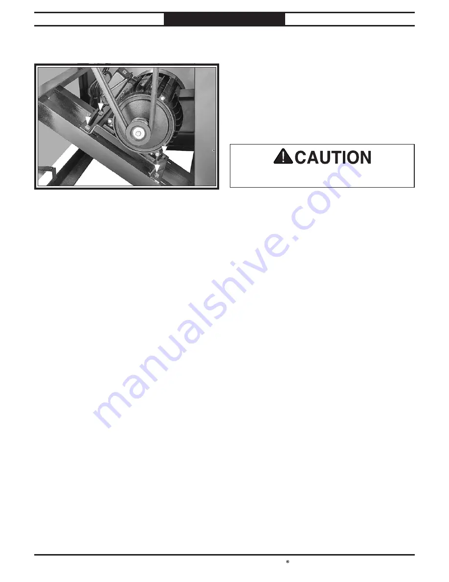
Loosen (4) motor mount hex bolts as shown
in Figure 50. DO NOT remove bolts!
Figure 50. Locations of motor mount bolts.
Figure 50. Locations of motor mount bolts.
Motor Mount
Motor Mount
Hex Bolts (4)
Hex Bolts (4)
To align pulleys:
Содержание SB1102
Страница 60: ...southbendtools com Printed In Taiwan JP21221...

