-32-
For Machines Mfd. Since 12/21
South Bend Tools
Model SB1102
S E R V I C E
Note:
The sanding drum should touch the
gauge blocks and still be able to rotate with
moderate force. The drum should touch the
gauges on both sides with equal resistance on
the both gauges.
— If drum is aligned equally on both gauges,
no adjustment is necessary. Proceed to
Step 7.
— If drum is not aligned equally on both
gauges. Proceed to Step 4.
10.
Using table depth scale, lower table (
1
⁄
8
) turn
from Reference Height #1 and mark location
of handwheel and table in relation to the
body of sander. Both these marks indicate
exact table position (referred to as Reference
Height #2).
11.
Lower table two full turns.
12.
Insert gauge blocks under rear drum, with
edge of block even with rear of table.
13.
Raise table to Reference Height #2.
14.
Loosen micro-adjustment lock levers, then
use micro-adjustment knobs to adjust rear
drum to gauge blocks until rear drum feels
and sounds similar to front drum.
Note:
Rear drum should always be slightly
lower than front drum, the actual difference
will vary depending on wood type, feed rate,
sandpaper grits, etc. Once familiar with the
adjustment process, experiment to determine
the best settings for your specific application.
6.
Lower table two full turns of handwheel.
Remove gauge block and re-insert it on left
side of table. Take care to line it up with
front of table just as it was done on previous
side.
7.
Raise table two full turns of handwheel to
bring it back up to Reference Height #1.
8.
Set height of front sanding drum to gauge
block.
9.
Rotate front sanding drum back and forth.
It should feel and sound as it did in Step 4.
If not, adjust drum height again. Continue
this process, going back and forth, until both
sides of drum feel and sound the same.
4.
Adjust height of right side of front sanding
drum so it just touches gauge block and is
able to rotate back and forth with moderate
resistance. Refer to Adjusting Drum
Height, the procedure that follows this one.
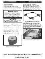
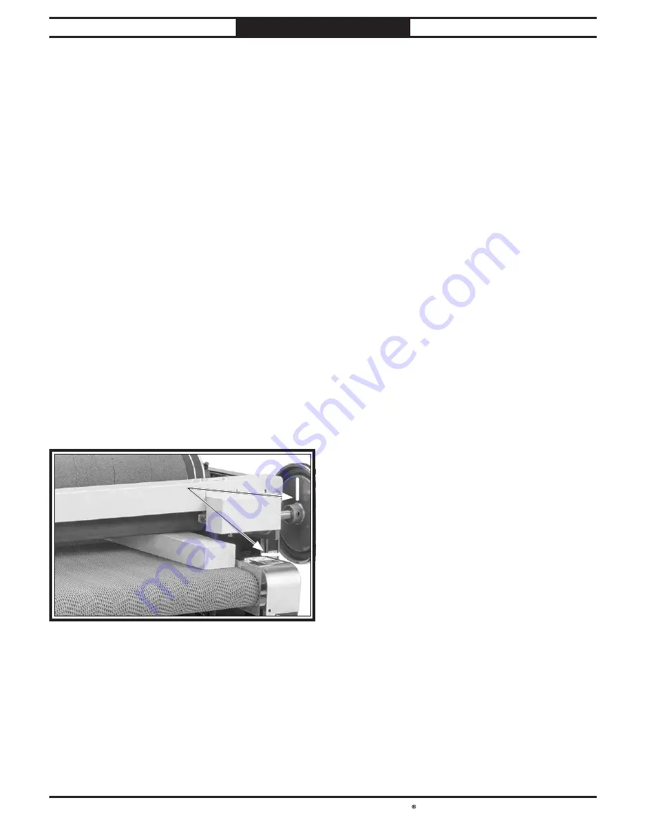
5.
Mark location of handwheel with a felt pen
or piece of tape. In same manner, mark
height of table in relation to the body of
sander. Both marks indicate exact table
position, referred to as Reference Height #1
(see Figure 40).
Note:
Having Reference Height #1 marked is
crucial to all subsequent steps.
Reference Height #1
Figure 40. Reference Height #1.
Figure 40. Reference Height #1.
Reference Marks
Reference Marks
Содержание SB1102
Страница 60: ...southbendtools com Printed In Taiwan JP21221...


